Repost - Earth Rod not taken account in TN systems

Hi All,

I realise the function of the earth rod in a TN system is to provide a close reference to true earth for the neutral

The thing that has confused me slightly is the TNCS PNB, which has an earth rod located at the consumer end. When i looked at the old forums there was a debate between whether this was TNCS or TNS, as the neutral carries no current due to the earth rod, and therefore by definition cannot be a combined conductor. If the current is not dissipated into the ground via the rod, why would no current flow in the neutral of this system prior to the rod

Thanks in advance

EDIT: My question wasn’t phrased very well and I’ve tried to clean it up for future readers, but i think this is the correct summary.

Fault current CAN flow between the neutral/earth link and the neutral point of the transformer in a PNB earthing arrangement. The previous forum posters were essentially saying is that even though though the link is remote, fault current will still flow in the CNE cabling, but we can note that it also would in a pure TN-S system but more likely an internal section of busbar within the TX and the neutral bar, instead of external cabling and by that logic TN-S would be a form of TN-C-S if semantics were involved.

Link to thread
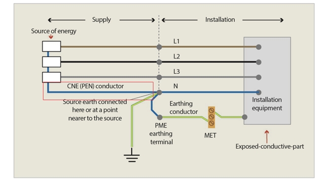
 What earthing arrangement is this? 

Parents
  • PNB is not a TT system - it's a TN system, which means that the fault current to PE (exposed-conductive-parts) travels back to the transformer neutral either via the separate protective conductor all the way (TN-S), or the separate protective conductor then the PEN conductor (TN-C-S).

    PNB comes in some different variants, some of which are shown in ENA Engineering Recommendation G12/5, although the actual diagrams on some DNO's web-sites provide much more insight into real arrangements of PNB.

    The difference with a PNB (TN-S variant) from a TN-S system, is that the electrode (and its connection to the Neutral) is not immediately adjacent to the LV side of the transformer, but happens some distance from the transformer (typically around 8-10 m or more), simply because the fault conditions on the HV side of the transformer will not permit the HV and LV earths to be connected at the transformer pole. In the TN-C-S variant, typically the earthing of the neutral happens at the first customer rather than along the LV line.

    Compare with TT system, where the fault current travels back to the transformer neutral down the consumer's separate PE conductor, then through the consumer's earth electrode, the general mass of Earth, then the distributor's earth electrode - hence the 'typical' quoted Ze for 100- A supplies being 21 ohms (not including consumer's earth electrode resistance).

  • Thanks Graham, that’s a helpful response. Ill look into those more detailed DNO images

    The reason my confusion came about from looking at an old forum discussion on whether PNB was actually TN-S or TNCS with well established members arguing that the CNE before the neutral earth link didn’t actually carry fault current. The leg I’m thinking of is attached in an image

  • In the above diagram you posted, the electrode is not on the consumer side, but the distributor's side.

    One of the issues in the industry, is that people have been taught that if there is an electrode at the consumer's premises, it's always TT. Whilst was easy to remember when passing exams, sadly, it is NOT ALWAYS the case (in fact, never was).

    The giveaway, is that there is an earthing conductor between the distributor's earthing terminal and the MET. Have a look at Regulation Group 542.1.2, which provides the clues you need. in TT and IT systems, the earthing conductor is connected to the consumer's electrode(s) ONLY, whereas in a TN-C-S or TN-S system, the earthing conductor connects to the distributor's earthing terminal.

    PNB of the variant shown in your diagram above (or as used in installations with a private transformer, and earth electrodes connected to the neutral at the main switchboard), is only one example of where a TN system has additional earth electrodes. An additional consumer's earth electrode may be provided by the consumer in their installation for any TN system (in fact, BS 7671 now has a firm recommendation for this, see Regulation 411.4.2, last para). Where the connected mode earthing arrangements are TN, additional earth electrode (or electrodes) is likely to be a firm requirement for an installation with island mode capability because of Regulation 551.4.3.2.1.

Reply
  • In the above diagram you posted, the electrode is not on the consumer side, but the distributor's side.

    One of the issues in the industry, is that people have been taught that if there is an electrode at the consumer's premises, it's always TT. Whilst was easy to remember when passing exams, sadly, it is NOT ALWAYS the case (in fact, never was).

    The giveaway, is that there is an earthing conductor between the distributor's earthing terminal and the MET. Have a look at Regulation Group 542.1.2, which provides the clues you need. in TT and IT systems, the earthing conductor is connected to the consumer's electrode(s) ONLY, whereas in a TN-C-S or TN-S system, the earthing conductor connects to the distributor's earthing terminal.

    PNB of the variant shown in your diagram above (or as used in installations with a private transformer, and earth electrodes connected to the neutral at the main switchboard), is only one example of where a TN system has additional earth electrodes. An additional consumer's earth electrode may be provided by the consumer in their installation for any TN system (in fact, BS 7671 now has a firm recommendation for this, see Regulation 411.4.2, last para). Where the connected mode earthing arrangements are TN, additional earth electrode (or electrodes) is likely to be a firm requirement for an installation with island mode capability because of Regulation 551.4.3.2.1.

Children
No Data