Repost - Earth Rod not taken account in TN systems

Hi All,

I realise the function of the earth rod in a TN system is to provide a close reference to true earth for the neutral

The thing that has confused me slightly is the TNCS PNB, which has an earth rod located at the consumer end. When i looked at the old forums there was a debate between whether this was TNCS or TNS, as the neutral carries no current due to the earth rod, and therefore by definition cannot be a combined conductor. If the current is not dissipated into the ground via the rod, why would no current flow in the neutral of this system prior to the rod

Thanks in advance

EDIT: My question wasn’t phrased very well and I’ve tried to clean it up for future readers, but i think this is the correct summary.

Fault current CAN flow between the neutral/earth link and the neutral point of the transformer in a PNB earthing arrangement. The previous forum posters were essentially saying is that even though though the link is remote, fault current will still flow in the CNE cabling, but we can note that it also would in a pure TN-S system but more likely an internal section of busbar within the TX and the neutral bar, instead of external cabling and by that logic TN-S would be a form of TN-C-S if semantics were involved.

Link to thread
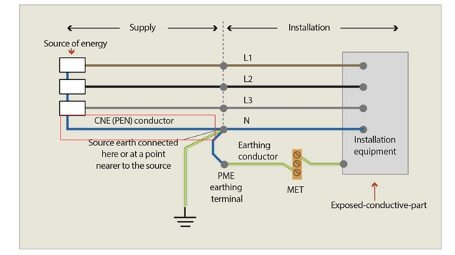
 What earthing arrangement is this? 

Parents
  • Hi, I did try and answer your previous post. The absence of current flow in the neutral of this system before the rod is due to the lack of potential difference between the neutral and the earth at that point. The PEN conductor is earthed at multiple points along its length, so it has a very low earth impedance. Consequently, there is no voltage drop along the PEN conductor, and no current flow between the PEN and PE conductors.

  • If you are referring to a TN-S system, then the fault current does not go through the ground at all, and it is dissipated as heat within the cabling until the ADS occurs. The earth rod does not impact the loop impedance calculation. If you are referring to a TN-C system, then some fault current goes through the ground via the earth rod, but it is still mostly dissipated as heat within the cabling until the ADS occurs. The earth rod does impact the loop impedance calculation. If you are referring to a TN-C-S system, then no fault current goes through either of the earth rods at both ends of the supply cable. The fault current is dissipated as heat within the cabling until the ADS occurs. The earth rods do not impact the loop impedance calculation.

  • Hi AMK, Thankyou firstly for the in-depth answer. 

    I think you may be on to something with the lack of potential difference between the star point of the TX, and the consumers neutral-earth link, and potentially explains why DNOs limit the length of this system to 40m to reduce the possibility of a rising voltage. For clarity its TNCS PNB I’m thinking about, I’ve highlighted the leg in the image below.

  • Hello Fiftyhertz, I appreciate your reply. BlushThe lack of potential difference between the star point of the transformer and the consumer’s neutral-earth link is correct. This is because the PEN conductor is connected to earth at both ends, creating a low impedance path for fault currents to flow. I agree this also explains why DNOs limit the length of this system to 40m, as longer cables may cause voltage drops and unbalance along the PEN conductor, affecting the supply quality and reliability.

  • I believe in the PNB arrangement, its only got the link at the consumers end of the installation, and this replaces the connection to earth at the star point in the TX spill box

  • There is a article titled “PNB arrangements – a new earthing arrangement for some DNOs”The article explains that the lack of potential difference theory may not hold in some cases, such as when there is a fault on the distribution network or when there are parallel paths for fault currents. Therefore, it is important to follow the guidance and precautions given by the DNO when installing or altering an electrical installation with a PNB arrangement.

  • One has to be careful when discussing faults to earth- there are two very distinct cases.

    1) We may mean faults to the earthed chassis of a piece of equipment,  such as when a washing machine or or a kettle fails - then the current is via the CPC, and in a TN-'x' where x is anything, there is an all-metal path from the live phase of the transformer to the fault, and on in the other side of the fault  an all metal path  of comparable resistance all the way back to the other side of the transformer. So 100A fuses can be blown, and traditional ADS works,

    2)  But there is a second class of 'fault to earth' even on TN-x which is where there is a fault to terra-firma earth but not the circuit CPC, such as the cut lawnmower cable  or damage to a double insulated tool that exposes a live part (garden tools are especially vulnerable) These faults always include the terra-firma earth path, rather than the CPC, and sometimes include a hapless person as well. Here the only reliable protection is the RCD,

    (Note that In TT the return path from the CPC also includes tens to hundreds of ohms of wet soil , and even with a solid  metal contact type fault the current will probably fire an RCD but only the smallest of fuses or MCBs...

    There is also another related nasty case worth a mention.

    Consider that the supply side earth electrodes may well only just make the 21 ohms for a lone 'pole pig' transformer in the country.

    Then if there is a fault that pulls one phase down much better than that - perhaps a fault from live to something that is a far better electrode than the DNOs one - and one  classic is the metal bodied barn with pile driven metal footings.. Now it is not the faulty installation that gets pulled to earth, but rather the phase,  Or to be more accurate, the full P-N voltage is split between the 2 electrodes and the ground between them and more of the volts are dropped in the ground near  the electrode with higher resistance. So everything that is earthed, or at least 'neutralled' to the supply CPC is now at some voltage well above terra-firma, and tingles and shocks will be reported from things in the installation that are working perfectly, while apart from a higher than normal meter reading, the fault may not be noticed for some time. Again RCDs save the day.

    Mike

  • “PNB arrangements – a new earthing arrangement for some DNOs”

    Interesting, the article must be 10s of years old! ... Nothing new, the arrangement has been used by DNOs for a very very long time.

  • ut there is a second class of 'fault to earth' even on TN-x which is where there is a fault to terra-firma earth but not the circuit CPC, such as the cut lawnmower cable  or damage to a double insulated tool that exposes a live part (garden tools are especially vulnerable) These faults always include the terra-firma earth path, rather than the CPC, and sometimes include a hapless person as well.

    Apart from additional protection, BS 7671 only covers faults of negligible impedance.

    The fault to Earth in the lawnmower example is only covered in BS 7671 once a person actually touches the live conductors during additional protection (give or take IT systems - but even then, only a fault of negligible impedance is considered). In general, apart from additional protection with the path involving a person, the fault path involving fault current Earth is really only considered for TT systems.

    Just to be 100 % clear, you might be lucky to get an RCD to trip when you cut a lawnmower lead before touching, but I'm pretty sure there are more cases than not where it takes human (or pet) contact to trigger the RCD.

Reply
  • ut there is a second class of 'fault to earth' even on TN-x which is where there is a fault to terra-firma earth but not the circuit CPC, such as the cut lawnmower cable  or damage to a double insulated tool that exposes a live part (garden tools are especially vulnerable) These faults always include the terra-firma earth path, rather than the CPC, and sometimes include a hapless person as well.

    Apart from additional protection, BS 7671 only covers faults of negligible impedance.

    The fault to Earth in the lawnmower example is only covered in BS 7671 once a person actually touches the live conductors during additional protection (give or take IT systems - but even then, only a fault of negligible impedance is considered). In general, apart from additional protection with the path involving a person, the fault path involving fault current Earth is really only considered for TT systems.

    Just to be 100 % clear, you might be lucky to get an RCD to trip when you cut a lawnmower lead before touching, but I'm pretty sure there are more cases than not where it takes human (or pet) contact to trigger the RCD.

Children
  • I would like to ask a question that may deviate slightly from the main topic, and that may have been addressed many times before. My question is about the appropriate method for sizing the bonding conductors for main extraneous conductive parts. Should I use PME or TN-S as the reference earthing system? The site where I mostly work has a private transformer and a PNB arrangement. According to the NICEIC guidelines, I should use PME, but the site engineer argues for TN/S. If I switch to PME sizing, the conductor size would need to be increased by 50% . Moreover, this change would affect all the buildings throughout the site.

  • ‘ECA Technical Guidance: When is TN-C-S PME and when isn’t it?’ States that if the neutral is controlled and the risk of loss is low in a true PNB System, it can be treated as per TN-S and TNCS PME bond sizes are not required

  • if the neutral is controlled and the risk of loss is low

    indeed - but turning that on its head if you cannot see/inspect it's full length maybe it isn't low risk so a transformer on your land, with no underground LV joints or overhead LV singles is OK - but anything else, well it becomes a matter of judgment, and recent NIC and NAPIT advice has been treat PNB like PME if in any doubt at all - which is probably sensible from their liability reduction perspective. Less useful if it is already there and you are wondering what to connect.

    Mike

  • I do consider PNB to be TN-S like, or at least more like TNS than TNC-s  I may be a minority !

    The part between the transformer star/ neutral and the first electrode is carrying current that is in perfect balance with the phase current (s) so In that sense it is carrying the fault current as well as the load current.  However, the same is true somewhere in the neutral path of a 'pure' TN-S as well.

    But the severity of breaking that extended transformer neutral connection is not the same as breaking a PEN in between two earthing points in a TNCs or PME system, as there is no-where that the chassis of equipment become live relative to terra-firma, In fact in a single phase PNB system, if you break the transformer neutral it is all quite safe, in a 3 phase PNB less so, delta connected loads will be fine but star connected ones will fight to pull the neutral off- balance. Again, the same risk is true of breaking the neutral in  TN-S.

    For me at least the thing that makes PME what it is is the 'M' - the multiple points where N and E meet. This is both the strength and the weakness - for if the CNE breaks between 2 such points then a lot of earthed metalwork is now very metallically connected to an off- earth voltage. This does not happen in TNS or PNB, regardless of which side of the one and only NE bond you sever the neutral.

     For me one could take a TNS and slide the point of separation along away from the TX, and it becomes PNB at some point,

    Also TNC-s is not always the same as PNB either, as we do not take the CNE all the way to the consuming loads or even multiple loads and split it there - the split is very much done at the origin of the distribution side of things.

    Mike.

  • My position is that PME and PNB are both subtypes of the TN-C-S earthing system. As you know, TN-C-S stands for Terra Neutral Combined Separate, which means that the supply conductor serves as both the neutral and the protective conductor, while the installation has separate conductors for these functions. The supply conductor is called PEN (Protective Earth Neutral) or CNE (Combined Neutral Earth), and the installation conductors are N (Neutral) and PE (Protective Earth) or CPC (Circuit Protective Conductor). The difference between PME and PNB lies in how the PEN or CNE conductor is earthed along the distribution network. In PME, the PEN or CNE conductor is earthed at multiple points, such as at the transformer, at the service cut-out, and at various places along the cable route. This reduces the resistance of the PEN or CNE conductor to Earth, and also provides a low-impedance path for fault currents to return to the source. However, this also creates a potential danger of touch voltage, which is the voltage difference between an exposed-conductive-part of an installation and a nearby earthed object, such as a metal water pipe or a fence. In PNB, the PEN or CNE conductor is earthed at only one point, which is far away from the transformer, between the transformer and the supply terminals of the consumer. This means that there is no other earth electrode along the cable route, and the resistance of the PEN or CNE conductor to Earth is higher than in PME. This reduces the risk of touch voltage, but also increases the risk of overvoltage, which is the voltage rise on the neutral conductor due to an open-circuit fault in the PEN or CNE conductor as you mentioned.

  • In PME, the PEN or CNE conductor is earthed at multiple points, such as at the transformer, at the service cut-out, and at various places along the cable route.

    I think of PNB as being PME for one consumer on the basis that there is nowhere for the multiple earths to be planted.

  • Good point, makes sense.

  • ‘ECA Technical Guidance: When is TN-C-S PME and when isn’t it?’ States that if the neutral is controlled and the risk of loss is low in a true PNB System, it can be treated as per TN-S and TNCS PME bond sizes are not required

    Interesting. Whilst that is true for private LV supplies (or where a private transformer is used), it doesn't align with ENA EREC G12/5 (and G12/4 before it) which states that PME conditions apply to PNB where the PNB earthing arrangement is in the distribution system. This is a very important consideration.

  • My position is that PME and PNB are both subtypes of the TN-C-S earthing system.

    That is definitely not always the case (regardless of whether we are talking about PNB in the public network, or from a private transformer. It's possible to arrange armour of cables so it's TN-S all the way pretty much!

  • I think of PNB as being PME for one consumer on the basis that there is nowhere for the multiple earths to be planted.

    This isn't true, PNB can supply up to 4 customers if used by DNO. There are different variants on how earthing is arranged, and whether a CNE (combined neutral-and-earth) is provided to the customer (and connected to the MET) or SNE (separate neutral-and-earth).