Repost - Earth Rod not taken account in TN systems

Hi All,

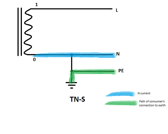
I realise the function of the earth rod in a TN system is to provide a close reference to true earth for the neutral

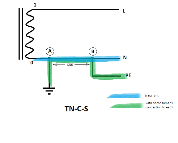
The thing that has confused me slightly is the TNCS PNB, which has an earth rod located at the consumer end. When i looked at the old forums there was a debate between whether this was TNCS or TNS, as the neutral carries no current due to the earth rod, and therefore by definition cannot be a combined conductor. If the current is not dissipated into the ground via the rod, why would no current flow in the neutral of this system prior to the rod

Thanks in advance

EDIT: My question wasn’t phrased very well and I’ve tried to clean it up for future readers, but i think this is the correct summary.

Fault current CAN flow between the neutral/earth link and the neutral point of the transformer in a PNB earthing arrangement. The previous forum posters were essentially saying is that even though though the link is remote, fault current will still flow in the CNE cabling, but we can note that it also would in a pure TN-S system but more likely an internal section of busbar within the TX and the neutral bar, instead of external cabling and by that logic TN-S would be a form of TN-C-S if semantics were involved.

Link to thread

 What earthing arrangement is this? 

Parents
  • I think most of the points have been already covered - just to add:

    1. Any electrode has a very considerable resistance to the general mass of the Earth - generally several tens of Ohms (with a lot of effort you might get down to an Ohm or slightly lower). It's all down to the soil that surrounds the electrode rather than the resistance metallic electrode itself. So two (or more) electrodes on the same PEN conductor normally make a very small difference indeed  (tens of Ohms in parallel with probably less than 1/10th of an Ohm) - for all practical purposes the effect on normal loop impedance etc. is ignored. Forget any notion of there being no potential difference along a N or PEN conductor - there will be if there's any N or PE current flowing - Ohm's Law still applies even if the numbers are small.

    2. To be TN-C-S there must be a conductor in the system that carries both N current and provides a connection to Earth. To my mind that's down to the order between the electrode and the N-PE link, so TN-S looks like this:

    and TN-C-S:

    The PEN (or CNE) conductor only exists between points A and B to my mind (not between 0 and A).

    Note that there's nothing in those diagrams (or BS 7671's definitions) that say how far apart the transformer, N-PE link and electrode can be.

    Also we're talking about the path of the connection of the installation to Earth rather than the route taken by earth fault currents (whose complete path will of course be back to the transformer star point). It's the presence of N currents between the installation and Earth that causes some of the biggest problems with TN-C-S, (especially during broken PEN events, but some smaller problems under normal conditions too).

    Take the TN-C-S diagram and add a few more electrodes to the PEN conductor and you have PME.

    PNB can be either (in the limiting case, a single bolt provides the N-PE link and the connection point for the electrode's conductor) so the cases converge - it can be argued either way).

    "PME conditions apply" typically means the "DNO want you to treat it as if it were PME" - whether it actually is at the present time or not - i.e. they're keeping their options open if they want to convert to fully fledged PME at a later date (typically to allow additional consumers to be connected to the same transformer in the future). Where there isn't a DNO involved on the LV side (e.g. industrial site with a private transformer) it's then feasible to adopt a TN-S version of PNB and not worry about PME conditions.

       - Andy.

  • what would be the deciding factors in you using this PNB TNS arrangement with the CNE? Probably length of run would be a factor 

    Or just DNO policy

  • what would be the deciding factors in you using this PNB TNS arrangement with the CNE?

    In TN-S there is no CNE.

    Have a search of old posts on the forum for examples of PNB style TN-S (it gets talked about quite a bit) - the classic is an industrial setup (with their own transformer) where the HV and LV earths need to be kept separate (usually because the HV earth isn't metallic all the way back to the HV source - i.e. there are overhead sections on wooden poles in the HV supply). In this case, the N-PE link and connection to the LV earth electrode is often done at the first tier distribution board - which is often a distance away from the transformer (e.g. in a LV switch room inside the building, whereas the transformer is outside across the card park somewhere, or at least in a different compartment). Many consider the arrangement to be pure TN-S - just with rather long connections to the transformer's secondary windings.

    As others have already mentioned, PNB is common for rural domestic supplies too (think a remote house or farm with a pole mounted transformer) - although typically the DNOs say that everyone should treat those as "may be PME in the future" so slap on PME conditions anyway.

       - Andy.

  • Hello Andy,

    Many thanks for this.  Earthing is one area where I find I need to "re learn" it every time I come back to it and so the community guidance I find very useful!

    GN-8 explanatory diagrams do seem to indicate that it is the path of the "Earth Fault Loop" current that is a deciding factor when considering what type of earthing system is in use (i.e. the red earth fault paths etc)...

    • TN-C - Earth fault current flows in the PEN all the way back to the source TX neutral to complete the circuit (TX Neutral earthed at star point)
    • TN-S - Earth fault current flows in the separate CPC all the way back to the source TX neutral to complete the circuit (TX Neutral earthed at star point)
    • TN-C-S - Earth fault current flows in the separate CPC but also relies on a PEN conductor to make it's way back to the source TX neutral to complete the circuit (neutral can be earthed at multiple points (PME) or a single point (PNB))
    • TT system - Earth fault is via separate CPC in the installation but via Terra back to the TX Neutral

    When you say:

    "To be TN-C-S there must be a conductor in the system that carries both N current and provides a connection to Earth. To my mind that's down to the order between the electrode and the N-PE link, so TN-S looks like this..."

    1. When I look at your sketch for TN-S it seems to be very close to showing the GN-8 figure 4.7 for TN-C-S albeit you are earthing the earth bar not the neutral directly?
    2. Also from the transformers point of view isn't the neutral wire in your sketch carrying both neutral current and providing a connection to Earth?(i.e. references TX neutral to "earth" potential for the installation)

    I work in industrial installations whereby we own and operate our own HV switches and transformers and regularly include N/E links in the LV panel.  In BS7671 it suggests that where you own and operate the transformers then the transformer and the LV bushings are considered part of the "installation".  

    Again I find this topic a challenge and so thought I would ask for clarification!

    Cheers,

    Rich

  • From the transformers point of view - and it may be easier to visualise with single phase, but the same is true of 3 phase, all return current comes back to the other end of the secondary winding - it cannot tell if it is 'fault' current or a legitimate load at  that point - just that the total winding current  had better add up to zero - in the sense that for any one winding, what goes in one end of it , had jolly well better match whatever comes out at the the other - it is just a wire wrapped around a magnetic stick after all...

    The is always  true of TT, TNS TNCs and indeed any transformer ..(on a non faulty transformer and ignoring displacement current/ inter winding capacitance effects)

    Once you get very close to the NE bond there is a fuzzy sort of bridge between TNC-s and TNS that can be almost at the level of what order the lugs are placed on the terminals, and depends on how many things need come undone before the system loses its terra-firma earth reference, and if it loses the neutral connection to the load first..

    You may at one extreme have a shared PEN that is really only the length of one bolt or one link bar between 2 studs. Or with the same hardware assembled in a different order, you may not have a PEN at all. Or as per the more textbook case, you may have a PEN that is many metres or even hundreds of metres in length.

    Mike

  • diagrams do seem to indicate that it is the path of the "Earth Fault Loop" current that is a deciding factor when considering what type of earthing system is in use

    I must confess I don't personally find that a useful definition - in all systems TN-S, TN-C-S and even TT, there's at least one conductor you could point at that carries both earth fault and N currents (e.g. between the point where the N is earthed nearest the source and the transformer winding) - which is why I prefer to think of a PEN or CNE conductor as both carrying N current and providing a means of earthing (as in a path to true Earth) for the consumer's installation.

    It's the N current flowing along the means of earthing for an installation (or in many cases, where a conductor is broken, not flowing but creating a substantial potential difference) that can raise consumer metalwork to hazardous voltages above true earth (or create substantial diverted N currents), that creates all the worrying problems with TN-C-S (PME) systems that means we have to treat them differently from TN-S or TT.

    In a classic PNB arrangement feeding a single consumer with the N-PE link between the N and electrode at the consumer's cut-out it's impossible to create the hazardous situations that can result from a classic broken PEN fault in a PME system - as if the supply N was broken all the consumer's earthed metalwork remains at 0V with no current flowing to change that.  As mentioned earlier by Chris Pearson though there is another variant of PNB - where the single point of earthing is out on a pole somewhere and L+PEN conductors run from there to two or more consumers who each have their own N-PE splits - which is most certainly TN-C-S has all the hazards of PME, but without actually being PME (because it's not multiply earthed). Hence most DNO's slap on the "PME conditional apply" requirement - and often do so in the simple case also, to allow them to reconfigure the supply in the future if necessary. Hence a lot of the confusion about exactly what is and isn't PME.

    The terms TN-S and TN-C-S, aren't directly equivalent to the DNO terms PME or PNB (or CNE and SEW - for separate earth wire - they're describing similar things but from quite different angles..

    Don't assume that wording in standards or textbooks is always perfect either - you only have to look over a few past editions to see how things change or are explained differently over time. These things are written by humans, and even ones in ivory towers err occasionally. Just look at how BS 7671 describes earth fault loop impedances - in 411.5.4 it includes the whole of impedance contributed by 'the source' whereas in the part 2 definitions it only mentions 'transformer winding' - the difference is perhaps minimal for the classic case of supplies direct from a large DNO transformer fed from a near infinite supply of the national grid, but for a small transformer deep in a consumer's installation, the impedance of the supply side L+N conductors will certainly limit the ability of the secondary winding to power an earth fault current - included by one definition but not the other.

       - Andy.

  • For me, this is clear TN-S as N current's can't affect the consumer's earth:

    and this is clearly TN-C-S - voltage drop along the CNE/PEN (between A and B) can raise the consumer's metalwork above true earth, and a break can make it instantly hazardous: Neither problems can arise in a TN-S system (at least not without multiple coincident faults):

    the more difficult to define is were there the two overlap - the point of earthing and the N/PE split are co-incident

    I'd probably suggest that the bolt that hold all 4 wires together, as a single point of failure, acts as a PEN conductor, to treat as TN-C-S.

       - Andy.

  • For me, this is clear TN-S as N current's can't affect the consumer's earth:

    If the "system referencing point" (connection with Earth electrode) is not at the transformer, then:

    • the portion of the N conductor between the system referencing point and the transformer '0' terminal is, strictly, a PEN conductor, because it earths the transformer - and usually the "can" of the transformer.
    • If any neutral current is flowing due to current from another installation, this effectively changes the neutral point of the transformer with respect to Earth. Perhaps less of an issue with single-phase than three-phase, but it affects the effective earth fault loop impedance.
    • If the neutral breaks between the system referencing point and the transformer, you will get similar behaviour to a broken neutral, but in this case, the transformer is unearthed. The neutral will be, and the fault may go undetected until there's a line to exposed-conductive-part (or cpc) fault ... and in that case, OCPDs provided for ADS may not operate, and touch-voltages may not be what you'd expect.

    So, I'm not 100 % sure it's always like TN-S?

  • because it earths the transformer - and usually the "can" of the transformer.

    I think that would be unusual - I thought Transformers are traditionally earthed to the primary circuit (which may well be combined with the LV earth on what used to be called 'cold' sites, but where they're separated, in all the cases I've seen it's been the LV earth that's at a distance).

    If the neutral breaks between the system referencing point and the transformer ... and the fault may go undetected

    Sorry, I'm probably not picturing this right,  It's a broken N, on a single phase system no current can't flow and the consumer will see it as a power cut. On 3-phase (or split phase) unless perfectly balanced it might be nastier and singe phase equipment seeing anything between 0 and 400V (or 460V) but again that tends to be noticed fairly rapidly.

       - Andy.

  • On 3-phase (or split phase) unless perfectly balanced it might be nastier and singe phase equipment seeing anything between 0 and 400V (or 460V) but again that tends to be noticed fairly rapidly.

    Yes, that's the point ... but if things are "balanced" it might not get noticed


  • but if things are "balanced" it might not get noticed

    Indeed, but is there a problem then? While it remains balanced both sides remain at 0V or thereabouts without needing a conductor. If an earth fault then occurs, then yes there may not be ADS (as there wouldn't be in any system if a protective conductor had previously failed) but in this case the consumer's metalwork remains substantially at 0V (as it's still connected to the electrode side of the break), so if anything as well as being pretty rare, it doesn't seem that bad compared to many 2nd faults.

       - Andy.

Reply
  • but if things are "balanced" it might not get noticed

    Indeed, but is there a problem then? While it remains balanced both sides remain at 0V or thereabouts without needing a conductor. If an earth fault then occurs, then yes there may not be ADS (as there wouldn't be in any system if a protective conductor had previously failed) but in this case the consumer's metalwork remains substantially at 0V (as it's still connected to the electrode side of the break), so if anything as well as being pretty rare, it doesn't seem that bad compared to many 2nd faults.

       - Andy.

Children
No Data