PEN protection - phase shift

Hello All,

Just reading this nice article on PEN protection:

https://electrical.theiet.org/wiring-matters/years/2021/84-march-2021/broken-pen/

Looking at implementing PEN protection as per BS7671: 722.411.4.1 - section (iii), which I believe allows for deriving a virtual neutral, which I thought could be done by looking at the L -> N phase voltages.

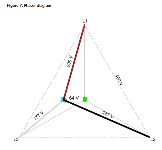
Figure 7 in that article shows a phasor diagram where L1, L2, L3 are 239V, 287V, 177V respectively, and shows a neutral shift of 64V. However if those phases are vector added assuming 120 degree phase shift, it's more like 95.5V.  I had to tweak the phase shift somewhat to get close to the 64V (0, 232, 113 degrees for instance).

Just wondering if my thinking is wrong, or in the event of a PEN fault could phase shift occur?

Thanks in advance.

Marty.

Parents
  • Just wondering if my thinking is wrong, or in the event of a PEN fault could phase shift occur?

    No, your thinking is not wrong. Phase-shift of the N with respect to L1, L2 and L3 DOES change in a broken neutral situation (not just broken PEN). It purely depends on the loads on each phase.

  • Thanks for your response. So yes I understand the neutral shift will occur, but wondering if the phase relationship between L1, L2, and L3 could change from 120 degrees?

Reply Children
  • wondering if the phase relationship between L1, L2, and L3 could change from 120 degrees?

    Not with respect to each other (unless there's another fault on the system).

    The transformer N is still connected to Earth, and that "fixes" L1 , L2, and L3 with respect to Earth. The Transormer also fixes the L1 and L2 and L3 with respect to each other.

    The issue here is that the N at the installation or loads is no longer connected to Earth.

  • Thanks again - in that case inclined to think there is an error on that phasor diagram.

  • Thanks again - in that case inclined to think there is an error on that phasor diagram.

    Why? It shows the three phases (that is phase voltages) at the corners of an equilateral triangle, so with respect to the centre of the triangle (true Earth), they are 120 degrees apart?

    I'm sure it's correct. The "shifted PEN" neutral (blue blob in the below) is NOT the transformer neutral (green blob in the below) which remains at true Earth.

  • The virtual N (blue bob) is the shifted neutral as you have said. However, as I understand it, the blue bob voltage (disconnected N - not earth) is the geometrical vector addition of the 3-phases? So we have:

    (239V, 0deg) + (287V, 240deg) + (177V, 120deg) = 95.52V, -85deg. (not 64V).

    However, if I tweak the phase offset slightly I can get closer:

    (239V, 1deg) + (287V, 234deg) + (177V, 113deg) = 65.1V, -89deg.

    Ps... understand phase order may be backwards but voltage is the same.

  • ah no - those 3 voltages are not at 120 degrees to each other any more. Consider the extreme of breaking L1 (imagine4 the fuse goes) while keeping L2, L3 connected. Now the floated earth is midway between 2 phases, and the voltages look like 200volts to 'earth' and  180degrees apart.

    Mike.

  • The virtual N (blue bob) is the shifted neutral as you have said. However, as I understand it, the blue bob voltage (disconnected N - not earth) is the geometrical vector addition of the 3-phases? So we have:

    That's not correct ... I think it's where you're going wrong.

    The virtual N (blue blob) is the vector sum of the voltages that develops across the impedances connecting each of the three phases to the PEN.

    The PEN is broken, so (worst-case) PEN current is zero, and therefore:

    iL1-PEN + iL2-PEN + iL3-PEN = 0

    (Lowercase i being a phasor current)

    If you know the actual impedances connected between each line and neutral, you can calculate iLx-PEN = (uLx-N - uPEN) / ZLx-PEN and calculate uPEN from the first equation (lowercase u being again a phasor voltage, so 230∠0 for L1, 230∠120 for L2 and 230∠240 for L3 - this is where the phasor vectors come from if the loads are resistive only)

    If the L-PEN impedances on each phase are identical, uPEN = 0 (i.e. same as transformer N)

  • Ah ok.. thanks Mike.

  • Ah that makes sense.