
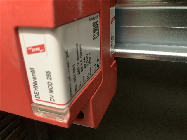
Located at intake and is Type 1. Has a Up of 1.5KV so can one assume it covers all categories set out in Table 443.2?
Hi Lyledunn. If The Up value is in accordance with the required withstand voltage of the equipment in the installation at that location then I would say it does. But only equipment at that location.It cannot eliminate the residual overvoltages that may affect the downstream equipment. Therefore, additional SPDs of Type 2 and/or Type 3 are required to remove the overvoltages downstream and provide a higher level of protection for the sensitive loads.
Hi Lyledunn,
Are you suggesting that the presence of a type 1 SPD would mean that it were safe to install OV category I equipment e.g. electronics without further protection? If so... I think that this is misreading the tables: Table 443.2 is a specification for the withstand capability of the various equipment types, which drives where equipment can be installed, whereas Up is the residual voltage after the nominal discharge. So they're not compatible for comparison and e.g. 534 should be used to select an appropriate SPD for sensitive equipment.
However, I think* that if I have the right part that device might in fact be a type 1 + 2 + 3 combined SPD, in which case this (but not the Up directly) would be reasonble grounds for determining that it gives protection to sensitive equipment within the switchboard... The difference between type 1, 2 and 3 is not just the voltage but the design impulse (current) also.
Apologies if I've misinterpreted your question.
*Do check!
There is a general point here - SPDs do not magically remove the spikes and replace them with smoothly polished bits of sine-wave to make up the gaps. (despite some makers literature.. )
What does happen is that the device has a high resistance at voltages up to some limit, and then as the voltage increases it starts to conduct with more and more vigour, until eventually it is practically a short circuit between the lines it is straddling, and the current is limited by external impedance (i.e. cable resistance and self inductance).
The effect is that the voltage across the device rises and then plateaus off at some higher than normal voltage but nothing like as high as if it had not been fitted.
Of course all sorts of voltage drop unpleasantness happens along the length of the wires carrying the kiloamps and the voltage drop is L*di/dt + I*R. You may know R, you probably do not know L, but a microhenry or so per meter of cable is about right more for wide spaced singles, and rather less where the 'flow and return' currents are organized to cancel each other's magnetic fields - like twisted pairs and coaxial cables. (think split con etc.)
This condition is only true for a very short time - if the transient lasts at the high level more than a few tens of microseconds the poor thing is blown to smithereens (energy = high current times high voltage times time and all that). And if that happens an even more unpleasant voltage spike appears in the lines that were just getting ramped up to carrying a few kA and suddenly are not (try stopping an express train dead once moving.)
So what are the grades meant to indicate - well the peak current and maximum times relate to the levels that it has been tested at without failure, (though other time/current waveforms that dissipate similar energy are likely to also be OK) and the peak voltage that exists while doing so.
Generally the bigger ones start to clamp at a higher voltage, but survive more violent events - hence the layered approach, so the one near the entrance takes the top off the really big hit as it comes in, but a few microhenries and milliohms away is a smaller one that takes that cut down spike and gives the remaining bump and any small spikes that the big one missed, a rather closer shave, so the overvoltage at the clean end is still less - but on its own that little one would not survive the same size worst case hit.
Mike
I find this entire subject rather confusing! May I check please?
I think that I understand the concept of cascading levels of protection so that a Type 1 SPD reduces the impact of whatever passes down a lightning protection system and is designed to protect the pretty robust stuff at the origin. If you do not have a LPS, you do not need type 1. Put another way, as Jam seems to be saying, the equipment at the origin needs to be able to withstand a relatively high impact voltage.
Type 2 deals with the lower voltage disturbances which come down the supply. They can let through enough energy to fry delicate equipment, which is where Type 3 comes in; however without Type 2 upstream, a Type 3 SPD on its own would be fried.
My main difficulty is with 534.4.4.2: "If the distance between the SPD and equipment to be protected (protective distance) is greater than 10 m ... Consideration should be given to the provision of additional coordinated SPDs ..."
I take this to mean that even if you have a Type 2 SPD at the origin (which lyledunn's may or may not be), if a distribution circuit is greater than 10 m in length, you need another Type 2 SPD at the next/final DB.
It also brings into question the purpose a Type 2 SPD at the origin if there is no sensitive equipment upstream of the DB which does supply it. Why not just install Type 2 SPD at the final DB(s).

My understanding of the Up categories for equipment (like computers) belongs to Category I (Table 443.2) which has a lower rated impulse voltage of 1.5kV for a 230V nominal voltage because it’s not generally as critical as the service entrance electricity meter which needs to be rated at 6Kv. This means the SPD with a Up of 1.5Kv can protect this equipment if it is connected at this point, because the SPD will turn on at 1.5 Kv and limit the overvoltage. Usually, this equipment is not close to the source and can have this lower category, unlike a meter which needs 6 Kv. I find this to be useful:

The 10m thing is due to the fact that (for reasons I don't pretend to comprehend) beyond 10m you can get some sort of ringing or resonance affect whereby the peak voltage may double. So if an SPD at a DB kind of reduces the spike to 1.5kV, then further than 10m away you may get a 3kV spike.
Type 1s are optimised for handling a long spike and are there to temporarily equipotentially bond the wiring system to the LPS system so that lightning is less likely to see a large PD between a cable and water pipe say, and thus arc between them, starting a fire. Because of that purpose, their response time and Up isn't optimised for protecting electrical equipment - that's what a type 2 is for, and why you need both. Of course, if its Up etc are within the spec for a type 2 as well, then it can be sold as a "type 1+2".
We're about to take you to the IET registration website. Don't worry though, you'll be sent straight back to the community after completing the registration.
Continue to the IET registration site
