
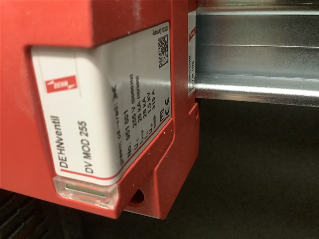
Located at intake and is Type 1. Has a Up of 1.5KV so can one assume it covers all categories set out in Table 443.2?
There is a general point here - SPDs do not magically remove the spikes and replace them with smoothly polished bits of sine-wave to make up the gaps. (despite some makers literature.. )
What does happen is that the device has a high resistance at voltages up to some limit, and then as the voltage increases it starts to conduct with more and more vigour, until eventually it is practically a short circuit between the lines it is straddling, and the current is limited by external impedance (i.e. cable resistance and self inductance).
The effect is that the voltage across the device rises and then plateaus off at some higher than normal voltage but nothing like as high as if it had not been fitted.
Of course all sorts of voltage drop unpleasantness happens along the length of the wires carrying the kiloamps and the voltage drop is L*di/dt + I*R. You may know R, you probably do not know L, but a microhenry or so per meter of cable is about right more for wide spaced singles, and rather less where the 'flow and return' currents are organized to cancel each other's magnetic fields - like twisted pairs and coaxial cables. (think split con etc.)
This condition is only true for a very short time - if the transient lasts at the high level more than a few tens of microseconds the poor thing is blown to smithereens (energy = high current times high voltage times time and all that). And if that happens an even more unpleasant voltage spike appears in the lines that were just getting ramped up to carrying a few kA and suddenly are not (try stopping an express train dead once moving.)
So what are the grades meant to indicate - well the peak current and maximum times relate to the levels that it has been tested at without failure, (though other time/current waveforms that dissipate similar energy are likely to also be OK) and the peak voltage that exists while doing so.
Generally the bigger ones start to clamp at a higher voltage, but survive more violent events - hence the layered approach, so the one near the entrance takes the top off the really big hit as it comes in, but a few microhenries and milliohms away is a smaller one that takes that cut down spike and gives the remaining bump and any small spikes that the big one missed, a rather closer shave, so the overvoltage at the clean end is still less - but on its own that little one would not survive the same size worst case hit.
Mike
We're about to take you to the IET registration website. Don't worry though, you'll be sent straight back to the community after completing the registration.
Continue to the IET registration site