
Not sure what to record! 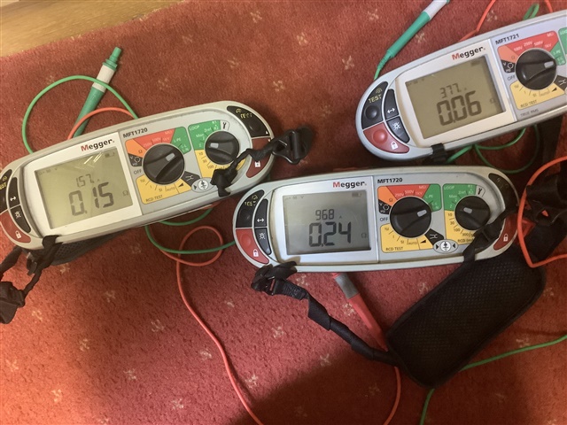
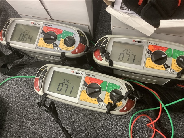
All calibrated around the same time. Three readings taken on each instrument with swapped leads and probes all fairly consistent with photo.
Then move to a socket opened up using same leads;
Not sure what to record!
How about:
a) <0.35 (tick)
b) <1.1 (tick).(or even <1667 (tick)).
After all the overall process is about showing the installation is safe, rather than being a box filling exercise and recognises the inherent variability in on-site measurement equipment.
(slightly tongue in cheek perhaps)
- Andy.
The value of 0.1 ohm given in GN3 may be a little optomistic, when you look at various manufacturers manuals.
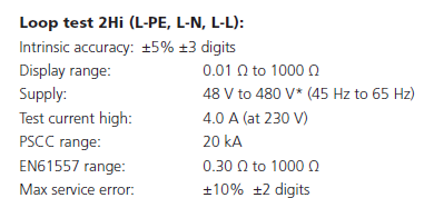
The manual for the Megger MFT1700 Series gives an operating range of 0.3 Ω to 1000 Ω for the high current loop test and 1 Ω to 1000 Ω for the low current loop test.
Taking the Fluke 1620 Series as another example, the operating range is given as 0.2 Ω to 200 Ω for the high current loop test and 0.4 Ω to 2000 Ω for the low current loop test.
And given that all the meters use something around 10-20A for the high current test, and something equivalent to 1/1000 of that for the low current no trip tests, even with a lot of re-measuring and averaging it is not too surprising - 0.3 ohms it is looking for a voltage change of a few volts on 230V or so, and the low current range is scrabbling about for some milli-volts.
With the best will in the world there will be situations where the supply is not clean enough to allow that voltage change to be estimated reliably,
The old analogue meters had the possible advantage that you could see it was all squished up at the infinity end of the PSSC scale, and you knew not to trust it. A digital device gives you a very precise but slightly different answer each time, but with no such caution to warn that PSSCs of 3000A and 6000A are actually almost indistinguishable from infinite.
Mike
Indeed Ross. So what does this reference to EN61557 mean in terms of function. Are we saying that any loop below 0.3 ohms might deliver unreliable results? At the lower loops, the instrument makes a simple ohms law calculation of Ipf which disregards the actual open circuit voltage and, of course, ignores the effect of reactance.
Ipf isnt really an issue in most installations using relatively modern equipment. 1000A + one way or the other is usually of no consequence. However, it does matter when we get to the Zs max for some high current MCCBs. It would seem to me that the MFT 1720 range is not the appropriate instrument when assessing such, but I always knew that.
The simple answer to the question 'Are we saying that any loop below 0.3 ohms might deliver unreliable results?' is yes.
The instrument is capable of indicating values between 0.01 Ω to 1000 Ω but the accuracy of the indicated value can only be relied upon in within the range 0.3 Ω to 1000 Ω.
The intrinsic accuracy is the accuracy expected under reference (laboratory) conditions whilst the maximum service error is the accuracy expected under actual (on-site) conditions.
The intrinsic accuracy is often the only factor contributing to the maximum service error that you can easily quantify or control.
At one time, manufacturers included information in their manuals showing how they calculated the maximum service error, taking into account factors such as ambient temperature, system voltage variation, system frequency variation and so on, but this doesn't seem to be as common now.
I dont have access to the EN 61557 series of standards right now, but if I recall correctly, the maximum service error permitted for most measurements is ± 30 % of reading.
To quote Megger in their own booklet on loop testing:
'As stated earlier in this booklet, we are not looking to venture into the physics of the testing, but suffice to say, when in close proximity of a transformer, the hand-held units available on the market today will struggle to return repeatable readings, when the calculated value is in the realms of milliohms and well below the stated range of the instrument'
We're about to take you to the IET registration website. Don't worry though, you'll be sent straight back to the community after completing the registration.
Continue to the IET registration site

