DP RCD for Solar PV?

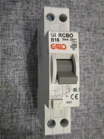
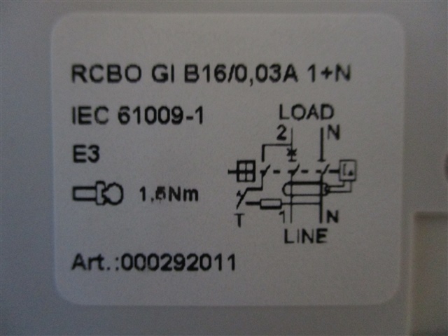
We are currently installing solar pv systems, and have had a third party at one of our installs carrying out an EICR. They have flagged a C2 for the RCBO we have used only being single pole.
In section 712 of BS7671 ‘Special Locations – Solar PV’ we cannot see a regulation that states that a double pole RCD is required. Any advice on this matter would be greatly appreciated.

Parents
  • www.beama.org.uk/.../BEAMA-Technical-Bulletin-Connection-of-Unidirectional-and-Bidirectional-Protective-Devices.pdf

  • Refer to the BEAMA guidance, it shows terminals marked Line and Load in your photo.

    www.beama.org.uk/.../BEAMA-Technical-Bulletin-Connection-of-Unidirectional-and-Bidirectional-Protective-Devices.pdf

  • As opposed to:

  • I think you should start worrying again. Contact the makers - it may just be a labelism or it may actually matter.

    is it the Garo one ?

    If so you are out of luck I am afraid.

    should have used  the two module width one


    Mike

  • I am getting a bit confused here. The BEAMA guidance refers to both MCBs and RCDs. I can see how an RCD in a split load CU could be run backwards (for want of a better description) but if the fault is before the RCD, it will not trip; and if it is after it, a fault in the consumer/meter/DNO tails seems pretty unlikely.

    Why would you connect a PV array to a final circuit which is protected by an RCBO? Is it not a distribution circuit, which accordingly, does not need RCD protection?

    What you might do is to put an RCBO downstream of the PV array, but the array would be connected to the supply terminals and the distribution circuit (to the CU) to the load side, so no problem there.

    Now think of night time. The supply side of the RCD is not energised. The load side is energised by the grid. So what are we worried about now? Is a fault on the wrong side of the RCD a realistic proposition?

    My apologies if I am missing something.

  • Well if the inverter makers instruction require it, it needs to be protected by an RCD (or double pole RCBO equivalent)...   But part of the problem  of inverters is that they do not generally provide enough over current relative to normal load current to operate conventional ADS in any sensible time, if at all. So for faults to earth, when running on an inverter derived supply, the RCD is needed to meet disconnection times. However, for systems that cannot run as an island, i.e, without grid power, it is not so important, as the grid always provides enough fuse-blowing current.

    However, one of the increasingly popular features of inverter PV, especially systems that include a storage battery, is the ability to operate as a generation island, and power essential functions in a power cut. In such a case, the RCD performs an ADS function, perhaps the only ADS function, depending on the strength of the inverter.

    Mike

  • Indeed. I still think there's room for confusion with my unit though.

    RCBO front view

    From the front you could believe it's bi-directional (no arrows or in/out or line/load markings) - although the 1 and 2 notation (which I think comes from a German convention for terminal markings might suggest line and load - on your bi-directional example both L terminals are marked 1/2). But then the label on the side clearly says line and load:

    RCBO label

    So the marking on the device itself seems contradictory. Personally, noting the 3rd contact interrupting the test circuit, which would seem to make the device immune to the problem Mike described, I'm inclined to believe it is bi-directional, but I'd be hard pressed to argue the case if someone pointed to the label and said otherwise.

       - Andy.

  • more importantly - the data sheet for it says in bold that the single module one isn't bi-directional but the double width one is - see my screen grabs from two posts above ;-)


    taken from this PDF.... www.garo.co.uk/.../uk pricelist 2022 april .pdf

    I suspect this is a subtelty of the electronic mechanisms that is only just becoming common knowledge, as text book, passive RCDs and  of course MCBs have no sense of supply and load-side.

    M.

  • Is it not a distribution circuit, which accordingly, does not need RCD protection?

    Would be needed for soft sheathed cabled concealed in walls (in my case I've used BS 8436 cable so I could get away without a 30mA RCD strictly speaking, but preferred to have it anyway).

       - Andy.

  • see my screen grabs from two posts above

    apologies - for some reason I didn't see that before I posted (not sure if due to my poor eye sight or the forum software).

    I'm pretty sure none of the manufacturer's instructions said that at the time - so might be a change of design or the later recognition of an older problem. I think I've got a 2-module one of a similar vintage so I'll see if I can dig a bit deeper (but probably not the right rating, so probably can't do a simple swap).

       - Andy.

  • The forum threading is a right pain actually, but that is a side track to the main discussion. I was not trying to tell you off, just to indicate that for GARO there is (in the current datasheets now at least, maybe not earlier ones) very clear advice .

    The earlier datasheet has the same terminal drawing you have on the side of your unit but is nothing like as clear - there is not the explicit statement about the line load allocation actually mattering that appears in the later document.

    It may be fun to power it from the wrong end and see how much current it draws when open and when shut, and  it may even be fun to trip it but I'd have a hand hovering ready to kill the power if it fails to trip in a second or so.
    M.

Reply
  • The forum threading is a right pain actually, but that is a side track to the main discussion. I was not trying to tell you off, just to indicate that for GARO there is (in the current datasheets now at least, maybe not earlier ones) very clear advice .

    The earlier datasheet has the same terminal drawing you have on the side of your unit but is nothing like as clear - there is not the explicit statement about the line load allocation actually mattering that appears in the later document.

    It may be fun to power it from the wrong end and see how much current it draws when open and when shut, and  it may even be fun to trip it but I'd have a hand hovering ready to kill the power if it fails to trip in a second or so.
    M.

Children
  • My enquiry to the manufacturer of my particular device has yielded an interesting reply - while they confirm it is not bi-directional, they suggest that as it's still working after several years of service (I've just run a full set of RCD tests to confirm that), they don't see any immediate safety issue - so basically no need to worry about it - but if I wanted to upgrade to meet current regs they'd recommend their two-module version.

    Which sort of leaves me wondering what the problem really is?

    (I'm reminded of my enquiries to a combi boiler manufacturer about converting the system to open-vented - they initially said no - when I asked why, the answer wasn't any particular technical limitation, just that they hadn't specifically tested it in that situation so were unwilling to guarantee that it would ... in practice it was of course fine. I might be being unfair though.).

       - Andy.

  • How often has the RCD ever tripped, and in what direction was power flowing when it did ? I'd not expect any damage under any conditions until it tries to trip. Have you tested it trips OK on the tester both ways round,.
    You may be right and it is just an example of stickerism and a lack of understanding by the makers of their own product,

    Mike.

  • As I think that Mike implies, that can perfectly simply be explained by no fault having occurred!

  • How often has the RCD ever tripped, and in what direction was power flowing when it did ? I'd not expect any damage under any conditions until it tries to trip. Have you tested it trips OK on the tester both ways round

    Many times, but only by T button or RCD tester - and almost certainly only when the PV wasn't generating (I wouldn't want to miss out on some of my home grown!). I may well have an experiment, but after I've swapped it for a two module one, so it won't be a disaster if I do fry it. Possibly a saving grace is that the PV system will shut down automatically on loss of main (after a few seconds) so that might limit the potential for burn out too. The 3rd contact in the test circuit also eliminates some failure modes.

       - Andy.