DP RCD for Solar PV?

We are currently installing solar pv systems, and have had a third party at one of our installs carrying out an EICR. They have flagged a C2 for the RCBO we have used only being single pole.
In section 712 of BS7671 ‘Special Locations – Solar PV’ we cannot see a regulation that states that a double pole RCD is required. Any advice on this matter would be greatly appreciated.
  • I can't think why it should object - it should be used to dealing with a.c. and even an ordinary inductive load will back-feed somewhat at some points in the cycle (that's where the "wattless" current goes after all). In a way parallel generators are just loads with a PF of -1.

    I can see that some might have a "right way around" in terms of which side of the contacts their internal electronics are powered from (and which side you can safely do an IR test when its in the OFF position) - but with parallel generators you can't really win on that score whichever way around they go (just settle for a least worst option).

       - Andy.

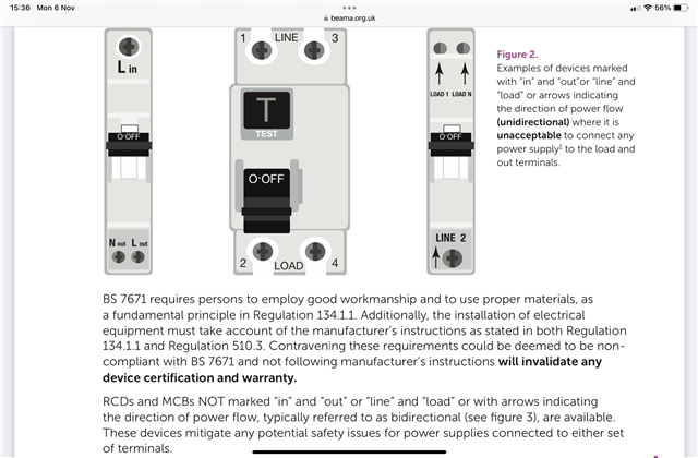
  • www.beama.org.uk/.../BEAMA-Technical-Bulletin-Connection-of-Unidirectional-and-Bidirectional-Protective-Devices.pdf

  • Thank-you that's interesting, very interesting. I wonder what the exact mechanism for causing damage to the device is. I'm having difficulty in imagining how arc chutes would be at all bothered if the voltage waveform happened to be out of sync.

       - Andy.

  • The BEAMA guidance was published a couple of months ago in August 2023.

  • Thank you for that. I have just checked and, happily, the MCB on a distribution circuit to my attic floor is bidirectional so I shall still be able to use it for a PV array.

  • I may be able to offer some clarification - all "electronic RCD" designs have a fairly bosky operating solenoid, and a series triac or similar high power semiconductor that acts as a switch to apply the L-N voltage to it to fire it.

    However, to make a coil that pulls in strongly with anything from the worst case drooping supply during fault, to the full 230V+10% needs quite a bit of space - but  the saving grace is that it does not need to be continuously rated, as after 40msec or whatever, the power is removed when the contacts open. (similar economies of rating  apply to the test resistors in some designs, and if for any reason the contacts do not open the resistor does instead...) so a coil  is wound that is OK for 60V steady state or something, and on full mains it is grossly over driven but for an acceptably short time.

    If the electronics that operates the solenoid is on the load side, then of course this all works really well, and the trigger circuit can simply come on and stay on, until the power goes off. Except, of course,  that if the supply is on the wrong side it never does go off, and the driver electronics and the coil slowly cook even after the contacts have done their thing.....

    It is not too hard to design electronics that removes the trigger signal after a certain interval and that can be relied upon regardless of supply direction, but it is a deliberate design decision to do that, and not one that all designs incorporate.

    (The apparently easy way would be to wire the trigger coil in the same way as the test resistor actually so that it gets its live from one side of the contacts and its neutral from the other - but there are also problems with  that sort of design in that it is possible to wire it up in a way that the neutral of the 'dead' side is then still connected to the live via the coil and the trigger after  it is supposed to have tripped. )

    Mike.

  • Thanks Mike - that makes a lot of sense.

    I've had a look at the type of RCBO that's on my PV system - looking  at the front  there was no indication of in/out or line/load - terminals just marked 2/N and 1/N so according to the BEAMA document I should be OK. I then noticed a label on the side that seems to suggest that 1/N should be line and 2/N load though (so should I start worrying again?)

    RCBO label

    Looking closely the test circuit does look to go through a 3rd contact so I guess they're recognised the problem and sorted it.

    Anyone got any ideas on the "arc extinguishing / short-circuit characteristics impaired" problem that the BEAMA document mentions?

        - Andy.

  • Refer to the BEAMA guidance, it shows terminals marked Line and Load in your photo.

    www.beama.org.uk/.../BEAMA-Technical-Bulletin-Connection-of-Unidirectional-and-Bidirectional-Protective-Devices.pdf

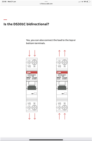
  • As opposed to:

  • I think you should start worrying again. Contact the makers - it may just be a labelism or it may actually matter.

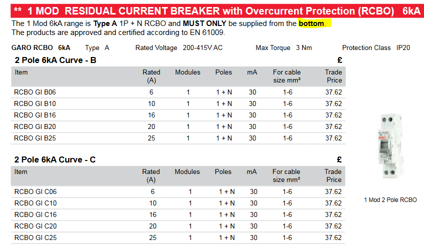
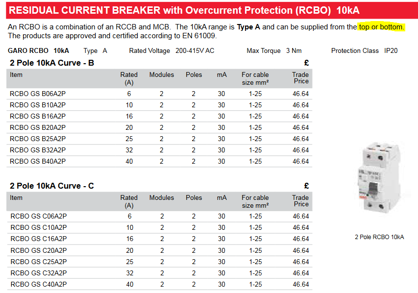
    is it the Garo one ?

    If so you are out of luck I am afraid.

    should have used  the two module width one


    Mike