
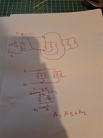
Am I correct in simplifying a ring circuit like this in theory? Assuming the loads are the same 1ohms and the distance between each load is the same as well.
Am I correct in simplifying a ring circuit like this in theory? Assuming the loads are the same 1ohms and the distance between each load is the same as well.
Not quite sure what you are asking.
Even radial circuits have loads in parallel.
The concept of a ring is that the resistance of the circuits is fairly constant throughout, although in fact the graph is a pretty flat elipse. The idea is that you have two circuits in parallel and as the resistance of one rises, the other one falls.
Unless you have a long thin ring (down a corridor, for example) they tend to use less copper than a radial.
Frankly, in some ways, they are more bother than they are worth.
yes.
To first go the wiring is zero resistance and all the loads are in parallel, getting the same 230V each or whatever. The currents add up, so that the current at the MCB is the total of all the loads.
To second order the wire is a very small resistance compared to the loads, and the voltage drop to each point on the ring is a function of the two parallel paths, one long and one short, to reach it and the loads that are dangling off en-route. Usually at this point we invoke superposition and calculate the ring with single point loads at various places and then add the contributions. or for the limit design, just assume that all the load is at the far end when both paths are half the ring length and equal - if that meets the voltage drop requirement, all other distributions of loads will be fine.
Occasionally folk worry about sockets very near the feed end of the ring, so that the current share is very unequal and then it may be possible to slightly overload the short path as that gets the lions share of the current.
Many years experience suggests this never happens in any normal household. Try and wire up a few 4mm radials, into single socket backboxes and you will appreciate the convenience of the 2,5mm ring.
Do be warned. It does seem that quite a number of folk do manage to cock-up the really simple ring concept and produce crab claws, or figure of 8s or spurs on spurs - I have a nasty feeling that this is not just kitchen fitters and DIYers who mostly get the blame but more than the odd 'professional spark' as well.
Not all that long ago I lent some test-gear to a friend with a really odd problem who eventually found a fused spur in the middle of his ring, wired to either close or open the ring depending on the state of the switch! Despite the obvious error It looked original, so one wonders about the quality of the installation inspection and test. Actually I don't really wonder, I know darn well that if the breaker stays on, and flames are not licking out of the side and there is no visible smoke, that is a clear pass for some down near the shallow end of 'operational excellence'...
Mike

Try and wire up a few 4mm radials, into single socket backboxes and you will appreciate the convenience of the 2,5mm ring.
Clearly there is more bulk. Another advantage of a ring is that BS 1363 sockets are required to accept only 8 mm² of copper so you can be sure of being able to spur off a ring, but not branch a radial.

Another advantage of a ring is that BS 1363 sockets are required to accept only 8 mm² of copper so you can be sure of being able to spur off a ring, but not branch a radial.
I would say that is not so much an advantage of a ring circuit but more a disadvantage of using parts that are too small to do what you want.
How do they determine the 8mm² of copper? 8 x 1mm², 2 x 4mm² plus the accompanying air gaps or what?

Well I was assuming that was a "thought experiment" by the original poster with easy numbers.
After all 250 A is a bit much for the 2.5mm2 and the 32a breaker! You probably get about 1/4 to 1/3 of a second before something lets go violently...
And, If it does not, then the company fuse will do the honours after a few seconds.
Mike.
Am I correct in simplifying a ring circuit like this in theory?
I'm not sure what your resistors represent - current using equipment alone, or the resistance of the ring conductors (wiring) as well.
If the former, then I'd say no, as you're not taking account of the two separate paths between CU and each load.
- Andy.
Spot on! I see that the Standard has been revised this year, but the provision has not changed. "12.5 Line and neutral terminals in fixed socket-outlets shall permit the connection, without special preparation, of one, two or three 2.5 mm² solid or stranded or of one or two 4 mm² stranded conductors."
Of course, the standard may be exceeded: better sockets will accept up to 12 mm².

Just out of curiosity, what does the new version say about PE terminal? I was disappointed that the MK socket with lever terminals couldn't accept 4 G/Y conductors of whatever size (e.g. two for the ring, one for a spur and one for the flylead to the back box). With screw terminals 4off 1.5mm² was a reasonable approximation to 3off 2.5mm² but that falls down when the lever terminals will only accept one conductor per hole.
- Andy.
We're about to take you to the IET registration website. Don't worry though, you'll be sent straight back to the community after completing the registration.
Continue to the IET registration site