contactor coils and a funny failure mode.

I have just changed a timer for an underfloor heating rig for the second time in less than 12 months. As far as  I can tell it has hardly been used - but like all things MAPJ1 there is a twist.

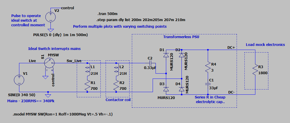
To save the thermostat (rated at '16A' and a very feeble looking relay) the heating of about 20A is switched by a couple of relays, and they in turn are operated by that thermostat. but the supply they switch  comes from a pair of changeover contactors that switch between Daytime and Economy 7 power, depending on the press of a 'day boost'  over-run timer.


The contactors are Garo 20A units and work seamlessly, and the thermostat and the two relays have been faultless - but the over-run timer has now failed twice, both times when the day time power has been switched off.

My unproven suspiscion is that this occurs when the contactor coils lose supply, but the heating resistance is not in parallel due to a satisifed thermostat.

Now I have heard figures of  an inductance of 20 henry in series with a few hundred ohms for single module contactors, but I have not yet measured these units to see how true this is.

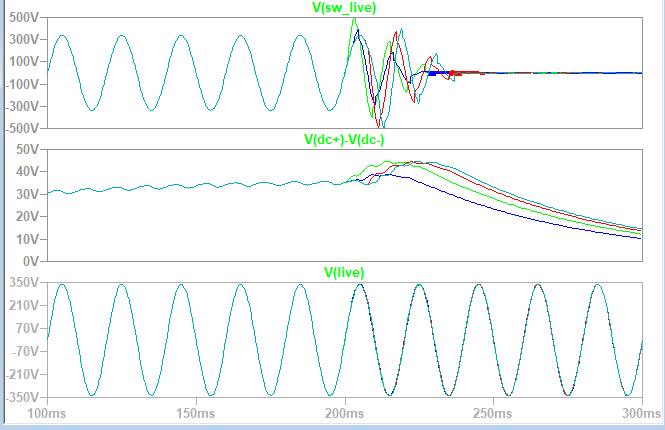
If so the kick from the contactors when supply is removed may be quite noticable, (stopping ~ 40mA each though a pair of  20H inductor I think is 33mili joules. ) but is it enough, really, to break an electronic timer.?

It does not feel quite right.

Has anyone else seen commercial grade  electronics in the vicinity of a contactor fail suddenly  when the supply stops, or analysed the back EMF kick back from contactors to see if that anecdotal figure is way off beam ?

Mike.

(yes I'm going to add a transorb anyway - I'd just like a warm feeling it was perhaps going to do some good.)

Parents
  • Hoping it may inform  or at least entertain,  I have decided, as I sometimes do, that modelling in Spice is my friend

    And err yes it  predicts a noticeable spike on the switched mains to ~ 500V, the  polarity and exact shape varying with instant of switching.
    The 24V DC for the relay and electronics internals, already a little high when the coil relay in the timer is off, (and sensibly about 24V when it is on) goes up to about 45- 50V.. Remember this feeds the 5V regulator. Ouch.
    The various different coloured sweeps are moving the instant of switching through the mains cycle, but generally the effect is fairly similar
    The resistor that is the in model to represent the electronics when the relay is off  is not quite right, hence the slope on the DC prior to the transient, but the over-voltage  effect is pretty clear.

    Well, my gast has been flabbered.... 
    Mike.

Reply
  • Hoping it may inform  or at least entertain,  I have decided, as I sometimes do, that modelling in Spice is my friend

    And err yes it  predicts a noticeable spike on the switched mains to ~ 500V, the  polarity and exact shape varying with instant of switching.
    The 24V DC for the relay and electronics internals, already a little high when the coil relay in the timer is off, (and sensibly about 24V when it is on) goes up to about 45- 50V.. Remember this feeds the 5V regulator. Ouch.
    The various different coloured sweeps are moving the instant of switching through the mains cycle, but generally the effect is fairly similar
    The resistor that is the in model to represent the electronics when the relay is off  is not quite right, hence the slope on the DC prior to the transient, but the over-voltage  effect is pretty clear.

    Well, my gast has been flabbered.... 
    Mike.

Children
  • Thats very interesting Mike.  I had some similar problems with a timeswitch failure a few years ago which on reflection might well have had the same cause.  All said though, we might reasonably expect modern electronics to withstand the sort of overvoltage your model is showing.   500V peak transients are probably quite common on UK supplies anyway especially with modern drives.

  • Interesting to have the anecdotal evidence that others have seen problems too.

    Suggests contactor coil  kick back is an effect worth considering and trying to design out around kit like this.

    yes - it is not really a massive over-voltage is it  ?- not even really enough to get a type 2 surge arrestor out of bed, so one of those would not  cut it down very much (though in this case it is on the wrong side of the interruption anyway). I'm pertty sure the mains is often quite furry at the 500V level. Interestingly the capacitor in the transformerless supply that gets the mains is X2 type rated for 330V so not a huge amount of of slack.

     In that case R-C snubbing accross the contactor coils may actually be better. Just need the resonance of the L of the contactor and the snubber C to be not too far from 50Hz and the sine wave will carry on and die out gracefully.

    I find myself  thinking that if I'd made something that easily upset as part of the day job, I'd be told to redesign it pretty sharpish ;-)

    Consumer electronics is a different world.

    Mike.

  • The transformerless ("capacitive dropper") power supply doesn't look like it has a current limiting resistor in it.  It's common to place a resistor (often a fusible resistor) in the mains supply, of maybe a few tens of ohms.  That tends to reduce current surges from step changes in the mains voltage, such as when plugging the thing in.  For some reason, it seems normal to put the capacitor in one leg of the power supply, and the resistor in the other.

  • Hi Simon, actually that is one of a number of economies in my model ! In reality there is a tubular MELF style ten ohm resistor which probably limits things in the tens of uSec timescale. Given the self resistance of the solenoids I did not think it would matter.

    The transients in this model are longer lived, and look like half cycles of the 0,33uF ringing in a rather low Q way with the two lots of 21H.

    I have since re-simmed with the resistor added, and I cannot see any great change to the effect on the DC output.  Really it needs a clamp on the DC side or a reg with a higher rated DC input,

    It is also possible that the ideal switch is too good, and few makes and breaks to represent a scratchy break would be more realistic.

    Mike

  • In all the 24V capacitive droppers I've fixed, domestic and commercial,  there has been a 1W 24V zener keeping the input to the regulator IC clamped. The zener has always failed short circuit and this results in the X2 cap getting warm. 

    I recently fixed a commercial watt meter which worked fine until the inverter feeding it dropped out of bypass. The meter was universal input 100-250V but at the 250V end the zener was over current. I wondered if harmonics played a part in this too.

    The regulator is probably a AMS1117 which has a typical maximum input of 30V but it varies a bit between manufacturers. 

    I've had problems using RC snubbers across relay contacts in the past as they will partly energise the load, thus adding to the power consumption. If you reduce the capacitor value too much they become ineffective.  Try a transorb across the contactor coil. 

    I agree that the internal timer relays look small for the rating, and you have to carefully read the datasheet. It will be derated for inductive loads, often considerably.

  • Further interesting anecdotal evidence of  design edge operation,  thankyou. 

    A 24V 1 watt zener becomes maxed out at 40mA, and that is if the PCB pads can be kept cool.

    If the cap is similar to mine (0.33uF 20% )  or larger, I can see how the zener has little  slack to handle transients on a hot day or if the unit is fitted in an airing cupbard or something.

     (Vishay datasheet )

    I can also imagine that a trapzoidal waveform that some inverters generate would not give the same dissipation

    splitting the heat between a pair of  12V ones in series would be a better call, or engaging a resistive idle load when the relay is not energised.

    Mike.

  • I tend to fit a 3W zener; but 2 in series is better for heat dissipation.

    I struggle to understand why commercial products are designed with such a poor power factor. A wattless design I measured (timer plug) consumes 0.6W and 30VA. The focus seems to be 'billable' power rather than the reality that the generator still has to provide the VA. As these are shunt regulators they consume broadly the same power with or without the relay energised.

    The better solution is something like this https://www.power.com/products/linkswitch which is claimed to have an improved power factor.

  • I must admit I was not (yet ) worried about the VA of the transformerless supply.  As far as I am aware there is no legislatve or CE mark driven  incentive to bother with measureing or specifying a PF at all on anything dissipating less than 100watts. I guess it gets compensated by   inductive power factor of contactor coils in my case,  or in many situations the average (inadequatly compensted) fridge ;-)

    I can well believe your results though - in big handfuls a 24V supply in which  of the incoming 230V the thick end of 90% of it (230V - 24V...) gets  dropped in a capactor  cannot do better than a PF of 0.1. can it ?


    Just thinking of I2,R dissipation versus CV2,/2 stored capacitive energy. I appreciate that I am mixing things measured in RMS and peak, but the implication of unavoidably poor PF is clear.

    I do wonder about the combined effects of corridors of a great many LED lights with capacitive droppers as well, even though I much prefer them to lines of screaming SMPS types and their combined EMC emmissions.

    Mike