contactor coils and a funny failure mode.

I have just changed a timer for an underfloor heating rig for the second time in less than 12 months. As far as  I can tell it has hardly been used - but like all things MAPJ1 there is a twist.

To save the thermostat (rated at '16A' and a very feeble looking relay) the heating of about 20A is switched by a couple of relays, and they in turn are operated by that thermostat. but the supply they switch  comes from a pair of changeover contactors that switch between Daytime and Economy 7 power, depending on the press of a 'day boost'  over-run timer.


The contactors are Garo 20A units and work seamlessly, and the thermostat and the two relays have been faultless - but the over-run timer has now failed twice, both times when the day time power has been switched off.

My unproven suspiscion is that this occurs when the contactor coils lose supply, but the heating resistance is not in parallel due to a satisifed thermostat.

Now I have heard figures of  an inductance of 20 henry in series with a few hundred ohms for single module contactors, but I have not yet measured these units to see how true this is.

If so the kick from the contactors when supply is removed may be quite noticable, (stopping ~ 40mA each though a pair of  20H inductor I think is 33mili joules. ) but is it enough, really, to break an electronic timer.?

It does not feel quite right.

Has anyone else seen commercial grade  electronics in the vicinity of a contactor fail suddenly  when the supply stops, or analysed the back EMF kick back from contactors to see if that anecdotal figure is way off beam ?

Mike.

(yes I'm going to add a transorb anyway - I'd just like a warm feeling it was perhaps going to do some good.)
Parents
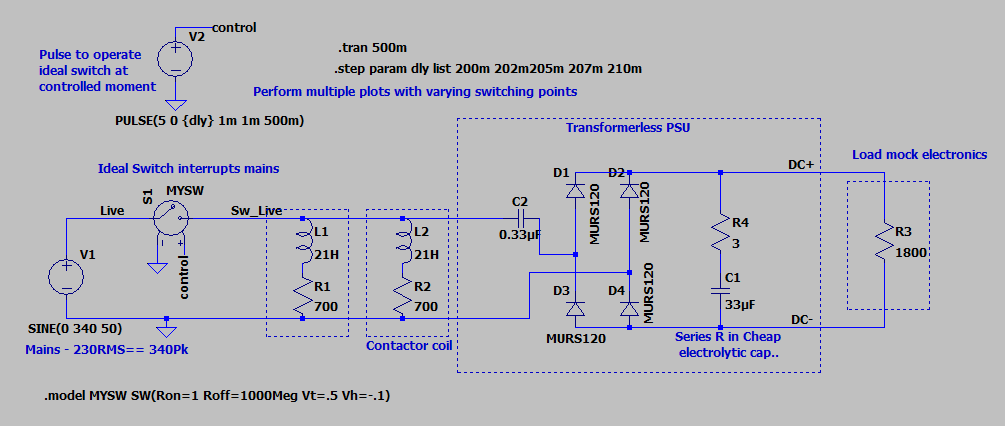
  • Hoping it may inform  or at least entertain,  I have decided, as I sometimes do, that modelling in Spice is my friend

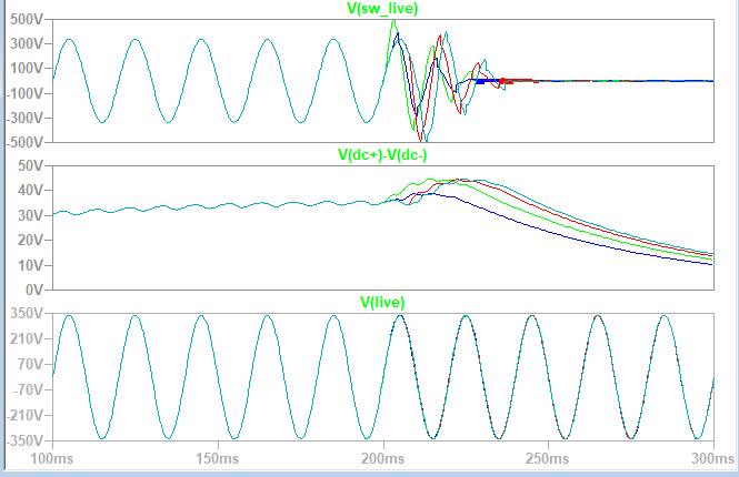
    And err yes it  predicts a noticeable spike on the switched mains to ~ 500V, the  polarity and exact shape varying with instant of switching.
    The 24V DC for the relay and electronics internals, already a little high when the coil relay in the timer is off, (and sensibly about 24V when it is on) goes up to about 45- 50V.. Remember this feeds the 5V regulator. Ouch.
    The various different coloured sweeps are moving the instant of switching through the mains cycle, but generally the effect is fairly similar
    The resistor that is the in model to represent the electronics when the relay is off  is not quite right, hence the slope on the DC prior to the transient, but the over-voltage  effect is pretty clear.

    Well, my gast has been flabbered.... 
    Mike.

  • Thats very interesting Mike.  I had some similar problems with a timeswitch failure a few years ago which on reflection might well have had the same cause.  All said though, we might reasonably expect modern electronics to withstand the sort of overvoltage your model is showing.   500V peak transients are probably quite common on UK supplies anyway especially with modern drives.

  • Interesting to have the anecdotal evidence that others have seen problems too.

    Suggests contactor coil  kick back is an effect worth considering and trying to design out around kit like this.

    yes - it is not really a massive over-voltage is it  ?- not even really enough to get a type 2 surge arrestor out of bed, so one of those would not  cut it down very much (though in this case it is on the wrong side of the interruption anyway). I'm pertty sure the mains is often quite furry at the 500V level. Interestingly the capacitor in the transformerless supply that gets the mains is X2 type rated for 330V so not a huge amount of of slack.

     In that case R-C snubbing accross the contactor coils may actually be better. Just need the resonance of the L of the contactor and the snubber C to be not too far from 50Hz and the sine wave will carry on and die out gracefully.

    I find myself  thinking that if I'd made something that easily upset as part of the day job, I'd be told to redesign it pretty sharpish ;-)

    Consumer electronics is a different world.

    Mike.

Reply
  • Interesting to have the anecdotal evidence that others have seen problems too.

    Suggests contactor coil  kick back is an effect worth considering and trying to design out around kit like this.

    yes - it is not really a massive over-voltage is it  ?- not even really enough to get a type 2 surge arrestor out of bed, so one of those would not  cut it down very much (though in this case it is on the wrong side of the interruption anyway). I'm pertty sure the mains is often quite furry at the 500V level. Interestingly the capacitor in the transformerless supply that gets the mains is X2 type rated for 330V so not a huge amount of of slack.

     In that case R-C snubbing accross the contactor coils may actually be better. Just need the resonance of the L of the contactor and the snubber C to be not too far from 50Hz and the sine wave will carry on and die out gracefully.

    I find myself  thinking that if I'd made something that easily upset as part of the day job, I'd be told to redesign it pretty sharpish ;-)

    Consumer electronics is a different world.

    Mike.

Children
No Data