This discussion has been locked.
You can no longer post new replies to this discussion. If you have a question you can start a new discussion

Reverse Polarity

Has anyone encountered a reverse polarity single phase PME supply to a house? If so, how did it happen and how was it detected?

I am intrigued to how you would discover it by measuring L-N, L-E, and N-E at the incoming side of the Main Switch, as the Earthing conductor would be connected to the Line at the cut-out and give 0V, the same as if it were correctly wired and you were measuring N-E?

I cannot get my head around how you would detect the issue.... maybe I will set it up on an empty standalone C/U and see what I get?

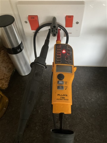
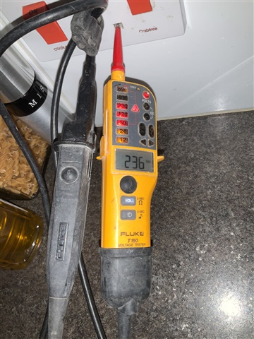
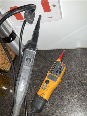
  • Fluke T150 with the batteries out and in, as well as batteries in but only single pole contact, there’s audible warnings as well with the batteries in and the option for a low impedance tests which gives visual, audible and tactile warnings as it vibrates as well as buzzing and lighting up.

    The tip shrouds were only removed for those particular tests and have been refitted.

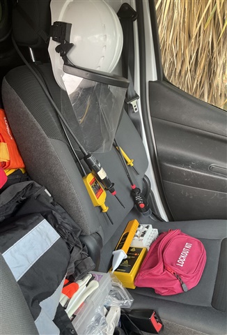
  • A genuine picture of the front seat in my van, these are additional items to those in my tool bag which includes two Fluke T150 voltage testers which give a single pole voltage indication and other lock offs.

  • A full test kit is required:

    • Two pole approved voltage tester.
    • Voltage tester proving unit.
    • Non-contact voltage indicator..
    • A single pole contact voltage indicator that can be used whilst wearing PPE.

    https://martindale-electric.co.uk/product/smkit5-smart-meter-installation-kit/

    They can be bought as a kit or as I did individually. Having worked on some scary installations, I have acquired a selection of voltage testers, I have encountered reserved polarity on the meter tails and within the installation, but never on the DNO network.

  • So L and N are reversed.

    Possibly better to describe as L-PEN (or L-CNE) reversal.

       - Andy.

  • Thankyou for all the comments. My main concern would be with a Line to Neutral reversal of a PME supply somewhere external to the property (e.g. DNO network), which would not be obvious or detectable by visual inspection during initial verification of a new electrical installation. I am struggling to see how the standard method that an electrician would undertake when checking for correct 'Live' Polarity at the origin (testing L-N and L-E = 230 V, N-E = 0 V) would highlight the problem?

  • Yes - the effect of other 'earthy' connections to to the MET is something I didn't take into account in the simplified model above.

    I thought that GN3 contained a note about verification of the polarity of the incoming supply - however, if it ever did it must have only been in older editions as it doesn't seem to appear in the current edition?

  • Does that help at all?

    Not always ... because if the MET is connected to extraneous-conductive-parts, all sorts of strange things start to happen. Sometimes, things will appear "normal", at others it can appear that exposed-conductive-parts have a (sizeable) voltage with respect to extraneous-conductive parts (or the "floor").

  • The neutral and 'earth' of a PME supply are common in the DNO service head, so if polarity is reversed at or before that point, the neutral and 'earth' will be at the same potential and the voltage measurements between phase, neutral and earth will all appear correct :

    L-N = 230 V   L-E = 230 V   N-E = 0V

    However, if the voltage measurements are made with reference to an independent earth electrode 'X' :

    L-N = 230 V   L-X = 0 V   N-X = 230 V   and also   E-X = 230 V

    Does that help at all?

  • it depends which 'E' you mean Chris, the CPC one that is derived from the PME neutral and appearing on the top of the 3 pin sockets, will be at neutral potential and no fault will be detected on the meter.

    However, the one that comes in via the plumbing will be a 'terra-firma' earth and will indeed correctly indicate the reversal.

    As others have said, it is where the CPC/ equi-potential zone meets the true earth - outside taps, EV chargers, outside lights and lamp posts etc are where the error will first be spotted.

    Also we tend to assume that the DNO earth electrodes always give a  better (lower resistance) earth connection than the bonding  at the load (property).

    That is not always the case, especially with modern plastic clad cables or overhead supplies, especially with some steel pile building constructions.

    In that case when the 230V is split between the DNO electrode and a large local electrode - either by design or accidentally by structural bonding,  it may be that the local earth looks OK, and everyone else on the substation gets shocks from the CPC , The larger fault current means the neutral (star) point of the transformer is pulled a long way off true earth. (In extremis you could imagine the corner of the 3 phase delta being earthed at the load, instead of the centre star, so that you have one phase near earth, the  neutral of 230, and the other 2 phases at  about 400V)

    Lots of current then flows in the earth between the house and the transformer but as none of it is via a meter, it may take some time to get tracked down,

    Rare but not unknown.

    Mike.

  • So L and N are reversed.

    Normally, L-N and L-E = 230 V, N-E = 0 V.

    When reversed, L-N = 230 V, L-E = 0 V, N-E = 230 V.

    If I am missing something, I apologise.