Unfamiliar electrical schematic symobol

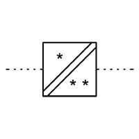
I've been working with electrical schematics for quite some time, but I recently stumbled upon symbols representing loads that I'm not familiar with. Are these new additions or have they been around, and I've somehow missed them? Any insights would be greatly appreciated. Thanks!

 

Parents
  • I've seen this (and one with two lines) used to represent a power converter with isolation (separation) - so this could represent protective separation.

    However, these usages are not in one of the official libraries other than for transducers/signal converters:

Reply
  • I've seen this (and one with two lines) used to represent a power converter with isolation (separation) - so this could represent protective separation.

    However, these usages are not in one of the official libraries other than for transducers/signal converters:

Children
  • Hi, thank you for your reply and for confirmain that it seems to be a non-standard use of the symbol and not just me. That is interesting, I wonder if they are using it to illustrate the individual isolators. I will have to go back to the project consultant and ask what they mean by it. 

  • Hi Alistair,

    The use of the symbol is standard to me (Building Services) .  I wouldn't read anything in to the rotation of it other than someone  copying the symbol from a layout where it was rotated to a wall or some other CAD mis-step.