Unfamiliar electrical schematic symobol

I've been working with electrical schematics for quite some time, but I recently stumbled upon symbols representing loads that I'm not familiar with. Are these new additions or have they been around, and I've somehow missed them? Any insights would be greatly appreciated. Thanks!

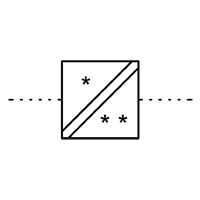
 

  • Without seeing the context, I have seen that or similar  used for relay or contactor coils. Not for resistive loads.

    M.

  • I've seen this (and one with two lines) used to represent a power converter with isolation (separation) - so this could represent protective separation.

    However, these usages are not in one of the official libraries other than for transducers/signal converters:

  • Hi, Thanks for your reply. Please see the image below for a little more context. 

  • Hi, thank you for your reply and for confirmain that it seems to be a non-standard use of the symbol and not just me. That is interesting, I wonder if they are using it to illustrate the individual isolators. I will have to go back to the project consultant and ask what they mean by it. 

  • Looks like a TPN isolator to me, but rotated 90 degrees from it's normal orientation.

  • Hi Alistair,

    The use of the symbol is standard to me (Building Services) .  I wouldn't read anything in to the rotation of it other than someone  copying the symbol from a layout where it was rotated to a wall or some other CAD mis-step.

  • Looks like a TPN isolator to me

    Apologies, but that is NOT the symbol for an electrical disconnector (isolator, or isolating swich).

    The "isolation" indicated with the box symbol in the OP is "separation" ("insulation") ... a very different concept.

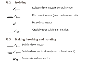
    A "single-line" or "schematic" version would be one of the symbols shown in J.3.2 of J.3.3 of IET Guidance Note 1, perhaps with "TPN" or "5P" (for 5-pole) next to it:


    BS 7671 (Regulation 514.9.1) requires symbols on diagrams to conform to IEC 60617, so the use of the symbol in the OP for a disconnector type isolator (isolating switch) in a schematic or SLD is a non-conformity with BS 7671.

  • Not saying you are not correct, but I suspect the OPs drawing was not a schematic wiring diagram, but a stage 3 or 4 design LV schematic aligned with BSRIA BG6 levels of detail.    Every LV schematic i have seen of this type has included the 'layout' symbol for the connection devices at the end of a line - e.g. see the distribution boards in the OPs picture - hence why i suspect the symbol has been copied from a layout, where it was showing an isolator on a wall running top-to-botom on the page and not rotated

  • Not saying you are not correct, but I suspect the OPs drawing was not a schematic wiring diagram, but a stage 3 or 4 design LV schematic aligned with BSRIA BG6 levels of detail. 

    Please don't get me wrong, I'm not targetting criticism with the last post - it would be rare to come across diagrams that fully conformed because of "house standards" and the fact that to get access to the official IEC 60617 library is a huge cost.

    In reality, doesn't matter whether it's wiring or schematic, the symbols in IEC 60617 are the same, as there are only two groups of symbols, one for architectural (positioning) drawings, and one set for schematic/wiring, although in reality they are for some symbols exactly the same.

    Importantly, though, from a CDM perspective, if this is supposed to indicate an isolator (provided for safety), it's important to make sure someone working with this at the next stage is aware of that? Surely, this thread is a good example of why we need to adopt standards for drawings?

    Incidentally, on the "slightly amusing" side, I think we mis-use the socket-outlet symbol on architectural (positioning) drawings, because the socket-outlet symbol is the single-line diagram symbol for a "socket contact" if you will, meaning the wiring goes in the back, and the "outlet" is the open side of the cup. We usually see these with the open side of the "cup" facing the wall (try and get your plug in there !):

  • We usually see these with the open side of the "cup" facing the wall (try and get your plug in there !)

    If the cup is facing the wall, the symbol looks more like a plug with a stump of flex.