Unfamiliar electrical schematic symobol

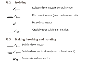
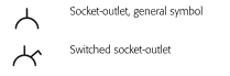
I've been working with electrical schematics for quite some time, but I recently stumbled upon symbols representing loads that I'm not familiar with. Are these new additions or have they been around, and I've somehow missed them? Any insights would be greatly appreciated. Thanks!


Parents
  • Looks like a TPN isolator to me, but rotated 90 degrees from it's normal orientation.

  • Looks like a TPN isolator to me

    Apologies, but that is NOT the symbol for an electrical disconnector (isolator, or isolating swich).

    The "isolation" indicated with the box symbol in the OP is "separation" ("insulation") ... a very different concept.

    A "single-line" or "schematic" version would be one of the symbols shown in J.3.2 of J.3.3 of IET Guidance Note 1, perhaps with "TPN" or "5P" (for 5-pole) next to it:


    BS 7671 (Regulation 514.9.1) requires symbols on diagrams to conform to IEC 60617, so the use of the symbol in the OP for a disconnector type isolator (isolating switch) in a schematic or SLD is a non-conformity with BS 7671.

  • Not saying you are not correct, but I suspect the OPs drawing was not a schematic wiring diagram, but a stage 3 or 4 design LV schematic aligned with BSRIA BG6 levels of detail.    Every LV schematic i have seen of this type has included the 'layout' symbol for the connection devices at the end of a line - e.g. see the distribution boards in the OPs picture - hence why i suspect the symbol has been copied from a layout, where it was showing an isolator on a wall running top-to-botom on the page and not rotated

  • Not saying you are not correct, but I suspect the OPs drawing was not a schematic wiring diagram, but a stage 3 or 4 design LV schematic aligned with BSRIA BG6 levels of detail. 

    Please don't get me wrong, I'm not targetting criticism with the last post - it would be rare to come across diagrams that fully conformed because of "house standards" and the fact that to get access to the official IEC 60617 library is a huge cost.

    In reality, doesn't matter whether it's wiring or schematic, the symbols in IEC 60617 are the same, as there are only two groups of symbols, one for architectural (positioning) drawings, and one set for schematic/wiring, although in reality they are for some symbols exactly the same.

    Importantly, though, from a CDM perspective, if this is supposed to indicate an isolator (provided for safety), it's important to make sure someone working with this at the next stage is aware of that? Surely, this thread is a good example of why we need to adopt standards for drawings?

    Incidentally, on the "slightly amusing" side, I think we mis-use the socket-outlet symbol on architectural (positioning) drawings, because the socket-outlet symbol is the single-line diagram symbol for a "socket contact" if you will, meaning the wiring goes in the back, and the "outlet" is the open side of the cup. We usually see these with the open side of the "cup" facing the wall (try and get your plug in there !):

Reply
  • Not saying you are not correct, but I suspect the OPs drawing was not a schematic wiring diagram, but a stage 3 or 4 design LV schematic aligned with BSRIA BG6 levels of detail. 

    Please don't get me wrong, I'm not targetting criticism with the last post - it would be rare to come across diagrams that fully conformed because of "house standards" and the fact that to get access to the official IEC 60617 library is a huge cost.

    In reality, doesn't matter whether it's wiring or schematic, the symbols in IEC 60617 are the same, as there are only two groups of symbols, one for architectural (positioning) drawings, and one set for schematic/wiring, although in reality they are for some symbols exactly the same.

    Importantly, though, from a CDM perspective, if this is supposed to indicate an isolator (provided for safety), it's important to make sure someone working with this at the next stage is aware of that? Surely, this thread is a good example of why we need to adopt standards for drawings?

    Incidentally, on the "slightly amusing" side, I think we mis-use the socket-outlet symbol on architectural (positioning) drawings, because the socket-outlet symbol is the single-line diagram symbol for a "socket contact" if you will, meaning the wiring goes in the back, and the "outlet" is the open side of the cup. We usually see these with the open side of the "cup" facing the wall (try and get your plug in there !):

Children
  • We usually see these with the open side of the "cup" facing the wall (try and get your plug in there !)

    If the cup is facing the wall, the symbol looks more like a plug with a stump of flex.

  • What this shows me, to work safely with customers or contractors digrams, requires the diagrams to include a key.

    Mike

  • If the cup is facing the wall, the symbol looks more like a plug with a stump of flex.

    Just some context, this is schematically how a "plug contact" (bottom) in a "socket receptacle" (top) ought to be shown (ISO 7000 - 0354)

  • requires the diagrams to include a key

    Not required for the symbols that conform to the standards, though, only for symbols not conforming ? Or at least that's the idea.

    Not just being awkward, I've worked with schematics that would require sheets for the key alone, and to keep referring back isn't productive.

    Same with colour code that's been harmonized for a very long time now - why do people invent their own?

  • probably in some cases because the standard is not readily available - see  that thread about free standards, and in the case of colour codes, has to suit the cable you can actually get- which in defence electronics at least  tends to be dominated by AWG sizes and US color codes. (red and black for DC +/- anyone ?

    And for things like logic symbols, because the BS ones are rubbish.

    M.

  • probably in some cases because the standard is not readily available - see  that thread about free standards,

    But we have been talking about an isolator symbol, which is shown in BS 7671 itself, and also in IET Guidance, so it's really not "hidden away" anywhere?

    Whilst it doesn't cover all the ISO 60617 symbols (the annual subscription for that being in the region of £600). most of the common ones can be found in the on-line browsing platform, e.g. for the symbols we are looking at, follow the link, click the radio button for "graphical symbols" and search for "disconnector"

    and in the case of colour codes, has to suit the cable you can actually get

    What I mean by colour codes, is the 2-letter colour code (4-letter for bi-coloured insulation) for wiring diagrams (say I have a 20-core cable that I want to connect for controls - you're not limited by colour except that GNYE is reserved for PE/PB (or combined PE+FE/PB+FB) and blue ought, as far as possible, to be used to refer to neutral (as defined in Part 2 of BS 7671).

    Following the lead of BS EN IEC 60445, We've put the BS EN IEC 60757 colour codes in Table 51.1 of BS 7671 now, so there really is no excuse regarding access to the standard when preparing diagrams:

    BK - Black
    BN - Brown
    RD - Red
    OG - Orange
    YE - Yellow
    GN - Green
    BU - Blue
    VT - Violet
    GY - Grey
    WH - White

    GNYE - Green-and-yellow

    And for things like logic symbols, because the BS ones are rubbish.

    Only because they are never taught. Just like most people would gravitate towards 'V=IR' rather than 'U=IR', and 'live and neutral' rather than 'line and neutral'

    Sometimes the ANSI "NAND" or "AND" symbols end up being used for socket-outlets on architectural layout drawings/floor plans.