Assessment of Protective Measures for an 12kW Electric Boiler Installation

I seek your insights on an observation made during an Electrical Installation Condition Report. A 12kW electric boiler has been installed within the electrical meter cupboard, in proximity to the consumer unit. The installation incorporates 16mm tails drawn from the line side of an 80Amp RCD housed in the installations split consumer unit feeding an additional 63amp 61008 RCD positioned within 3 meters, with the 12kW boiler directly connected to the load side.

The boiler is a fixed load and reliant on the Distribution Network Operator’s protective device for protection against overload and short circuit (L-N) fault currents. There were no evident signs of thermal overloading on any devices. It seems that earth fault protection is managed by the additional 63 Amp RCD within its own enclosure, while protection against overload and short circuit fault currents is afforded by the DNO’s equipment. The prospective short circuit current at the boiler measures 0.793kA and the DNO’s device is a 100 Amp BS 1361 type 2B.

What are your thoughts on if there is a requirement for any remedial action based on these findings?
  • Single phase, no dedicated fuse, MCB or RCBO ? 

    Reminds me that at one time it used to be quite common to find cookers and showers on the wrong side of the main switch in the "shallow end" accommodation the days of the hot wire wylex boards. Rough. 100A is a very loose fit to the correct rating.

    Not good, and I suspect if the DNO were aware they'd be wanting it changed.

    I'd have preferred Henley blocks to split tails and an  MCB or RCBO in the box not just an RCD. I am not sure it is actually an immediate danger exactly but certainly a cowboy job of the 1st order !

    What else have they done wrong ? And is the plumbing actually correct - in terms of overflows pressure relief or whatever ?

    Mike

    minor typo edits.

  • Hi Mike, thanks for your response. To clarify, the system is single-phase supply and has a dedicated 61008 RCD, without an additional overcurrent protection device, only the bullet. The plumbing arrangements seem to be in order. I agree with you on the henly block arrangement is how it should have been done to start with. I suppose it will come down to what the DNO have to say about it. 

  • I am a bit surprised that there have been so few responses, but I am not sure what is what - a wiring diagram would have been useful.

    So where are the "16 mm tails" connected? Are they the sole item supplied by one of two 80 A RCDs, in which case I do not see the point of the second one? In any event, the sole means of overcurrent protection seems to be the DNO's fuse, which does not quite suit 16 mm cables.

    Where is the main switch in all of this? I doubt that the DNO would concern itself with whatever is downstream of that or indeed their own fuse.

    Isn't the remedy is a 50 A MCB in the CU?

    How big is the boiler, and how big is the meter cabinet? Are we talking about one of those white plastic things, or a purpose built one indoors?

    C2 or C3? In the absence of signs of overheating, I am not convinced that remedial action is required urgently, so C3 from me on the available information.

  • Hi Chris, thanks for your reply. To provide a clearer picture, the installation comprises a split board consumer unit, with a 100 A main switch. This unit is dual RCD split board. The board is fully populated. 16mm supply tails have been connected to the line side of the first RCD within the consumer unit. These tails are then extended through an remote RCD unit, which in turn is connected to the12 kW boiler.

  • I presume there's no DNO agreement that their fuse provides overload or fault protection to the heater circuit - so a clear BS 7671 non-compliance on that score.

    Physically, it looks like it might just scrape though for L-N fault protection (0.793kA equates to 0.29Ω which just matches my old OSG for 16mm² and 100A BS 1361) - although changes to Cmin and whether the measurements were made with the conductors warm or cold could swing things either way. For L-PE we cannot say without more knowledge (is the c.p.c. also 16mm²?) - for larger fault currents RCDs alone may well not be fast enough to protect reduced c.s.a conductors).

    Clearly a 100A doesn't normally protect 16mm² conductors from overload - but that then begs the question of whether overload protection is required. If it's a fixed load incapable of overloading, it may well not be required. Heating elements normally can't overload, but some internal faults (e.g. short part way along an element) can behave like overloads as far as the fixed wiring is concerned. A simple element in an earthed metallic jacket (like most mineral insulated elements) can't really short to another live conductor, or by-pass a section of element) (and if it shorted to the jacket, the RCDs should disconnect in this case). However a lot of higher power water heaters used uninsulated elements - so depending on how the elements are arranged and whether there's any internal overload protection, so again a bit more research needed.

       - Andy.

  • Hi Andy. Thank you for your insights. An EICR has been conducted, and I am currently examining this specific certificate. This particular observation requires coding (I will speak with the inspector in the morning). Presently, there are no indications of thermal overloading; hence, in accordance with Regulation 433.3.1 (iv), overload protection may be deemed unnecessary due to the fixed load nature of the system, which should disconnect within five seconds under fault current conditions (referring to time/current graphs). However, as far as I am aware, this has not been agreed to with the DNO I seek yours and others perspective (I realise this is difficult without seeing the install but if you can using the info provided) on whether this should be documented as non-compliance with the Electricity Safety, Quality and Continuity Regulations (ESQCR). Would it be appropriate to classify it as (FI), a (C2) defect, or a (C3) defect?

  • Two options for split boards: 2 cables from the load side of the main switch to the RCDs, or one looped from one RCD to the second. If the latter, that seems to require at least 48 mm² into the RCD, which must be a bit tight, assuming of course that the terminal capacity is 50 mm² (or greater).

  • how do you get to 48mm2 ? -

    There is no need for the load side to total more than the incoming side, and within the CU you don't need the meter tail "insulated and sheathed" style cable, so you can push the current rating of the link wires quite a lot, or indeed have silicone rubber  insulated wire as the latest Wyex RCBOs do, or even use solid enameled wire as the old 'Volex' split load  units did, and then your 3mm dia. (8mm2 or so) single is good for at least 60-80A continuous.. 

    I'm not condoning what has been done here, but small looking split load links  may not be as bad as they seem.

    Mike

    PS

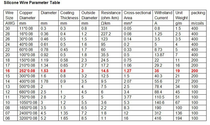
    Once you step away from the IEC derived limitation of a 70C or 90C copper temp, for insulation formulations  that can take it, the rating uplift is remarkable - here something near (but less than) 1.5mm2 is highlighted as fine for use at  up to 35A - because the insulation is fine with a copper core temp of about 150C. The insulation on the wire gets too hot to touch mind... And some of the enameled wires are good to even higher than that.

    Of course, at the ends it needs to connect to something solid that acts as a heatsink, or that does not mind getting equally hot, and that consideration is often the real limiting factor....

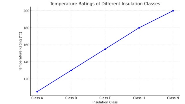
    Enamelled wire classes

  • how do you get to 48mm2 ?

    Presumably 3off 16mm² - we're told it's tee'd off the supply side of the 1st RCCB in the CU - so if the original internal rat's tails where 16mm² looped through to the 2nd RCCB - then adding another 16mm² brings it up to 48mm² (and probably in an odd shape too).

    whether this should be documented as non-compliance with the Electricity Safety, Quality and Continuity Regulations (ESQCR). Would it be appropriate to classify it as (FI), a (C2) defect, or a (C3) defect?

    Off the top of my head I don't recall a provision of the ESQCR it would be infringing (unless there was on-site generation, which implies a requirement to meet BS 7671).

    Presently, there are no indications of thermal overloading; hence, in accordance with Regulation 433.3.1 (iv), overload protection may be deemed unnecessary due to the fixed load nature of the system

    I'd be wary of assuming that just because it hasn't had a major overload so far that it's incapable of doing so in the future, but in general terms yes that regulation might apply (BTW I think it's (ii) in my book rather than (iv)). Really more information is required about the load to be sure either way.  Manufacturer's installation instructions might shed some light too.

    Without further information, I'd reluctantly say it would have to be a FI - hence a non-satisfactory, same as C2. Although some extra information (e.g. conductor sizes between RCCB and heater, incl. the c.p.c.) - that should be available to the inspector - might be enough to swing it to a definite C2.

    BTW do we know if the 12kW rating is for 230V or 240V?

       - Andy.

  • Hi Andy, must apologize for the current lack of information regarding the voltage rating. Subsequent to a consultation with the client, it has been decided that modifications will be implemented using Henley blocks, accompanied by the installation of an additional two-way consumer unit.