Assessment of Protective Measures for an 12kW Electric Boiler Installation

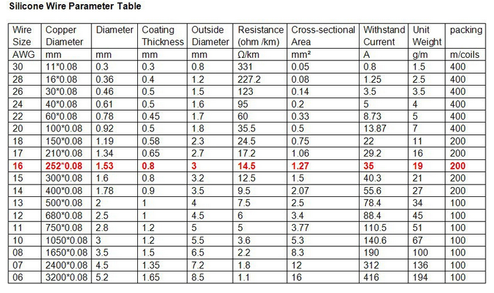
I seek your insights on an observation made during an Electrical Installation Condition Report. A 12kW electric boiler has been installed within the electrical meter cupboard, in proximity to the consumer unit. The installation incorporates 16mm tails drawn from the line side of an 80Amp RCD housed in the installations split consumer unit feeding an additional 63amp 61008 RCD positioned within 3 meters, with the 12kW boiler directly connected to the load side.

The boiler is a fixed load and reliant on the Distribution Network Operator’s protective device for protection against overload and short circuit (L-N) fault currents. There were no evident signs of thermal overloading on any devices. It seems that earth fault protection is managed by the additional 63 Amp RCD within its own enclosure, while protection against overload and short circuit fault currents is afforded by the DNO’s equipment. The prospective short circuit current at the boiler measures 0.793kA and the DNO’s device is a 100 Amp BS 1361 type 2B.

What are your thoughts on if there is a requirement for any remedial action based on these findings?

Parents
  • I am a bit surprised that there have been so few responses, but I am not sure what is what - a wiring diagram would have been useful.

    So where are the "16 mm tails" connected? Are they the sole item supplied by one of two 80 A RCDs, in which case I do not see the point of the second one? In any event, the sole means of overcurrent protection seems to be the DNO's fuse, which does not quite suit 16 mm cables.

    Where is the main switch in all of this? I doubt that the DNO would concern itself with whatever is downstream of that or indeed their own fuse.

    Isn't the remedy is a 50 A MCB in the CU?

    How big is the boiler, and how big is the meter cabinet? Are we talking about one of those white plastic things, or a purpose built one indoors?

    C2 or C3? In the absence of signs of overheating, I am not convinced that remedial action is required urgently, so C3 from me on the available information.

  • Hi Chris, thanks for your reply. To provide a clearer picture, the installation comprises a split board consumer unit, with a 100 A main switch. This unit is dual RCD split board. The board is fully populated. 16mm supply tails have been connected to the line side of the first RCD within the consumer unit. These tails are then extended through an remote RCD unit, which in turn is connected to the12 kW boiler.

  • Two options for split boards: 2 cables from the load side of the main switch to the RCDs, or one looped from one RCD to the second. If the latter, that seems to require at least 48 mm² into the RCD, which must be a bit tight, assuming of course that the terminal capacity is 50 mm² (or greater).

Reply
  • Two options for split boards: 2 cables from the load side of the main switch to the RCDs, or one looped from one RCD to the second. If the latter, that seems to require at least 48 mm² into the RCD, which must be a bit tight, assuming of course that the terminal capacity is 50 mm² (or greater).

Children
  • how do you get to 48mm2 ? -

    There is no need for the load side to total more than the incoming side, and within the CU you don't need the meter tail "insulated and sheathed" style cable, so you can push the current rating of the link wires quite a lot, or indeed have silicone rubber  insulated wire as the latest Wyex RCBOs do, or even use solid enameled wire as the old 'Volex' split load  units did, and then your 3mm dia. (8mm2 or so) single is good for at least 60-80A continuous.. 

    I'm not condoning what has been done here, but small looking split load links  may not be as bad as they seem.

    Mike

    PS

    Once you step away from the IEC derived limitation of a 70C or 90C copper temp, for insulation formulations  that can take it, the rating uplift is remarkable - here something near (but less than) 1.5mm2 is highlighted as fine for use at  up to 35A - because the insulation is fine with a copper core temp of about 150C. The insulation on the wire gets too hot to touch mind... And some of the enameled wires are good to even higher than that.

    Of course, at the ends it needs to connect to something solid that acts as a heatsink, or that does not mind getting equally hot, and that consideration is often the real limiting factor....

    Enamelled wire classes