So I'm trying to work out some cable calcs for a sub main leaving LV Side distribution equipment sited adjacent to a 800Kva transformer , any ideas what the Ze is likely to be ? I would think it will be really low
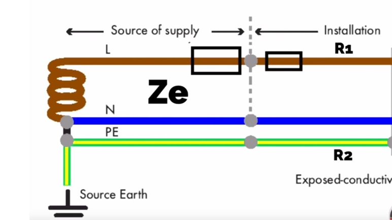
Well if you mean by 800kVA, one where the voltage drops by (say for an easy figures example) 5% at full load, you can immediately say that at 20 times that load current, 100% of the voltage is dropped, and under no condition will that fault current be exceeded, as that is the 'spanner on the terminals' condition. Then, as you move further down the sub main cables these conductors are added in the increasing fault loop, the Zs rises and the available fault current falls... as I'm sure you know.
So each line carries about 1200 amps full load, and if the droop was 5%, then the PSSC would be 24kA on any one phase, equivalent to a Ze of 9 milliohms (0.009 ohms)
Real transformers usually do a bit better than 5% output droop at full chat, but the fact the 5x20=100% makes for an especially easy illustration. The actual percentage is often printed on the transformer rating plate, if you can see it. An example from abroad with 4% internal impedance. (at 4% the ratio of steady state fully loaded current to the max fault current is 25, rather than 20, but the idea is the same)
![]()
Mike
Mike.
0.02 would be a bit high
But, 0.02 ohms might be the limit of the resolution of the instrument used, i.e. 0.01 ohms (rounded up) plus 1 in the last digit.
For measurements taken in close proximity to a transformer, a "normal" earth fault loop impedance tester is not always an appropriate instrument to use ... at least to get a "meaningful" reading.
In a recent inquiry with the DNO responsible for managing the substations on one of my sites, I obtained the following values for an 800 KVA transformer:
• Phase L1: 0.01 with a prospective short-circuit current of 20 kA
• Phase L2: 0.02 with a prospective short-circuit current of 15.1kA
• Phase L3: 0.01 with a prospective short-circuit current of 20 kA
With an 800 kVA transformer, I would have thought this would have been provided with an anticipated reactive component or phase angle to be of any real value (similarly, prospective fault current). Having said that, it's usually possible to develop these from a standard-type transformer model.
or measurements taken in close proximity to a transformer, a "normal" earth fault loop impedance tester is not always an appropriate instrument to use ... at least to get a "meaningful" reading.
Absolutely - as per a recent post about measuring low value resistances on earth clamps, beyond a certain point the reading eventually becomes a report of the instrument test leads and internal wiring - higher test currents and corrections for leads and probe/connection resistances are needed if it really matters.
If such a 'fruit machine' reading matters in practice or not rather depends on what the resulting figure is used for - for ensuring that the death or glory fuse will blow reliably, impedance just needs to be low enough, and not so low that when the fuse blows it does so so energetically that it takes something with it. The sort of fuses that should be used would normally energy limit, so the rating of switchgear and breakers further down stream is probably set by the choice of that first fuse, rather than just the transformer itself.
Mike.
Just to be clear. I only asked for Ze values for a particular substation with a 800kVA transformer
Understood.
"Z" has two components - resistive and reactive. Whilst it might be OK to provide 100 A supply Ze and assume x is approximately zero, It's not really a suitable answer to provide a "Ze" values for that size of supply in terms of resistance (or "magnitude") only.
We're about to take you to the IET registration website. Don't worry though, you'll be sent straight back to the community after completing the registration.
Continue to the IET registration site

