
I had an email this morning from the IET telling me that a Draft for Public Consultation has been published for Amendment 3 to BS 7671.
Details here electrical.theiet.org/.../
JP
I had an email this morning from the IET telling me that a Draft for Public Consultation has been published for Amendment 3 to BS 7671.
Details here electrical.theiet.org/.../
JP
Is that still the case, or could there be a 4th Amendment of the 18th?
It's not the case at the moment. It really depends on the extent of changes.
Large Amendments of course mean "new book" ... as does "new dated version" of BS 7671. Also, worth looking at "Edition" of the IET Wiring Regulations, vs a new dated version of BS 7671 - the 16th Edition was BS 7671:1992 and also BS 7671:2001, each of which had some amendments. However, the extent of changes made in 2001 led to the industry thinking that anyone who hadn't had an "update" course for 2001 needed extra tuition when it came to BS 7671:2008 update courses - but these decisions on required industry training/courses are, of course, totally divorced from developing and maintaining the standard itself.
Ouch, you're correct.
I was noticing the definitions wording which is limited to protective devices but proposed 530.3.201 as presently drafted has a far wider scope.
How can equipment for isolation possibly be directional? Thermonic emissions of electrons? Well if it's glowing there's bigger issues to worry about.

The proposed amendment BS 7671:2018+A3:2024 follows a BEAMA technical bulletin concerning connection of unidirectional and bidirectional protective devices such as Circuit-Breakers, RCDs and AFDDs to power supplies, such as PV inverters, Electrical Energy Storage Systems (EESS) and Vehicle to Grid (V2G) electric vehicles (EV).
The issue highlighted in the BEAMA technical bulletin is regarding the ‘line’ and ‘load’ convention. The relevant product standards, such as BS EN 61009 require protective devices such as RCBOs to be marked to indicate ‘line’ and ‘load’, or ‘in’ and ‘out’. The concern is that if a power supply, such as a PV inverter is connected to the ‘load’ or ‘out’ terminals of a unidirectional RCBO, parts of the electronic circuit can be damaged.
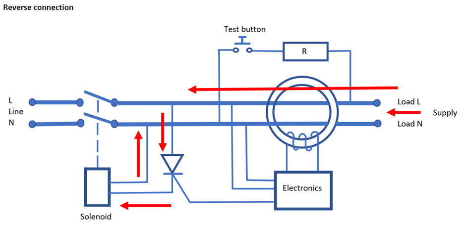
When a residual current is detected by the current transformer, a signal is sent to the electronics from the secondary winding, which in turn opens the gate of the thyristor and allows current to flow to the solenoid. This causes the solenoid to operate resulting in the operation of the switching mechanism and opening of the contacts which interrupts the current flow.
The important thing here is that once a signal enters the thyristor gate and activates the device, it will continue to pass current until the voltage drops below a specific level. In the event of an earth fault or using the test button, the RCBO will trip but there will still be a voltage present on the load terminals from the PV inverter resulting in current flowing through the thyristor and the solenoid being activated for an extended length of time.
The thyristor and solenoid are short time rated components, any delay in interrupting the supply will result in damage to these components rendering the residual current detection inoperable. The design of RCBOs will vary between manufacturers, the thyristor and solenoid are one example of the components that can become damaged.
Where Moulded Case Circuit Breakers (MCCBs) are reverse connected, their arc extinguishing/short-circuit characteristics could be impaired.
The diagram below shows reverse connection of a unidirectional RCBO.
I hope this is helpful.

I hope this is helpful.
Michael, it is indeed. :-)
What about ordinary (domestic/commercial/light industrial) MCBs?
I ask because the most suitable piece of roof of my house is adjacent to a DB, which is supplied through an MCB - no need for an RCD and the other circuits have RCBOs. If the wiggly amps can come back down those cables and back through the MCB for onward consumption elsewhere in the house (or further away), happy days!
(My MCBs are labelled, "2" and "1" for supply and load respectively, so all seems well.)
What about ordinary (domestic/commercial/light industrial) MCBs?
Domestic MCB's typically don't have any electronic controls in them unlike some MCCB's, but always check the MI's because someone is likely to have made one.
One thing that was missed [or not deemed relevant] by BEAMA and by Michael's excellent article in Wiring Matters [https://electrical.theiet.org/wiring-matters/years/2024/99-march-2024/bidirectional-protective-devices/] is that whereas RCBO's&RCD's may use a variety of terms to indicate directionality, an MCB/MCCB must use the arrow indication as the relevant standards for those devices dictate that an arrow must be used. I think it's worth noting.
The thyristor and solenoid are short time rated components, any delay in interrupting the supply will result in damage to these components rendering the residual current detection inoperable. The design of RCBOs will vary between manufacturers, the thyristor and solenoid are one example of the components that can become damaged.
This is very interesting. Although I've noticed that almost every RCCD on the market is bi-directional whereas RCBO's typically aren't - so my understanding from 61008-1 and 61009-1 was that when interrupting a fault of >1.5kA it would cook the electronics. But this got me thinking - RCCD's usually meet short circuit current withstand by coordination with a SCPD, and 61008-1 provides for this. But that particular test is performed with the SCPD upstream of the RCCD [See figure 7 BS EN 61008-1:2012+A12:2017] - the opposite of how we normally connect them.
I wonder how they would perform if that test was turned on it's head? Maybe RCCD's aren't quite as bidirectional as their MI's suggest?

How can equipment for isolation possibly be directional? Thermonic emissions of electrons? Well if it's glowing there's bigger issues to worry about.
A very simple example is a switch-fuse where the fuses remain connected to the pole side, where, to be able to replace fuses without operating another isolator, you'd of course want to connect a source to the switch-break side only.
With DC the arc is certainly directional, and one side of the contact gap is more consistently eroded by the arc than the other.

A very simple example is a switch-fuse where the fuses remain connected to the pole side, where, to be able to replace fuses without operating another isolator, you'd of course want to connect a source to the switch-break side only.
Fair point - and known issue when using single pole devices to feed 3-phase loads, for example. Which suggests again this is really a matter of voltages being present, rather than the actual direction of power flow.
As an interesting "historical curiosity" BS 7671 2008 contained: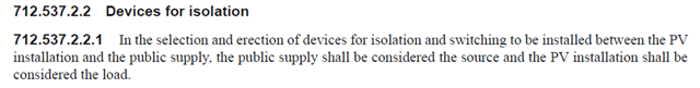
- Andy.
I hope this is helpful.
yes much so - thank-you!
Which then begs the question about other situations where the load side doesn't immediately become dead as soon as the device opens. E.g. feeding capacitive or inductive loads, or even decent sized motors that may gradually spin down over many seconds, acting as an impromptu generator. We've had many reports over the years of RCD testers being fooled into thinking RCDs haven't opened or opened too slowly by the effects of connected loads. If 0.5s PV disconnection times may be too long. a lot of these other sources presumably must be contenders too?
- Andy.
As an interesting "historical curiosity" BS 7671 2008 contained:
Agreed - that applied only to PV, and ONLY to devices for isolation and switching, NOT protective devices (even though they must also be suitable for isolation if used for ADS).
However, BS 7671 no longer has that requirement.
When a residual current is detected by the current transformer, a signal is sent to the electronics from the secondary winding, which in turn opens the gate of the thyristor and allows current to flow to the solenoid. This causes the solenoid to operate resulting in the operation of the switching mechanism and opening of the contacts which interrupts the current flow.
The important thing here is that once a signal enters the thyristor gate and activates the device, it will continue to pass current until the voltage drops below a specific level. In the event of an earth fault or using the test button, the RCBO will trip but there will still be a voltage present on the load terminals from the PV inverter resulting in current flowing through the thyristor and the solenoid being activated for an extended length of time.
I've been pondering this - and I'm not sure I'm convinced now. If I recall correctly from by PE mag days, the thyristor will turn off as soon as the current through it drops to zero - and as RCDs operate on AC that's every half cycle. So it can only overheat if the electronics continue to trigger the gate, which should only happen if there's an imbalance in the toroid.- which now there can't be as the only load on the mechanism side of the open contacts is the RCD electronics etc themselves - and that current (if the diagram is correct) should be returning through the toroid.
e.g. adding the return current to the diagram (orange arrow) we get:
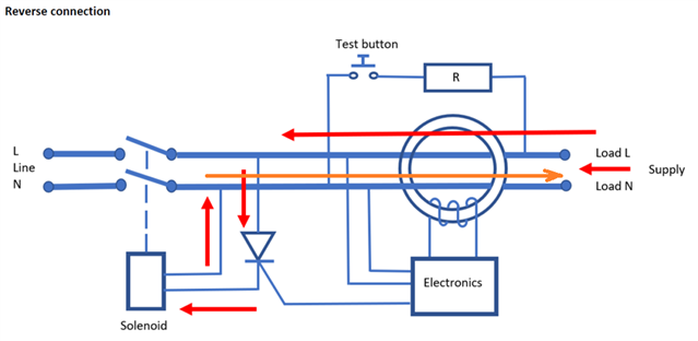
So at the moment I'm thinking that the electronics/thyristor/solenoid are in no more danger of overheating than they would be in normal service with the contacts closed - which hopefully is pretty negligible. Or I've missed something (again...).
- Andy.
We're about to take you to the IET registration website. Don't worry though, you'll be sent straight back to the community after completing the registration.
Continue to the IET registration site