
I had an email this morning from the IET telling me that a Draft for Public Consultation has been published for Amendment 3 to BS 7671.
Details here electrical.theiet.org/.../
JP
I had an email this morning from the IET telling me that a Draft for Public Consultation has been published for Amendment 3 to BS 7671.
Details here electrical.theiet.org/.../
JP
This post? WATCH THIS YOUTUBE VIDEO
Yes I agree, Mark Allison's Renewables Podcast was excellent.
I think what Graham and Michael have been doing is excellent and will lead to better standards and better observance of the standards.
I linked to the video below somewhere shortly after it live because I'd seen Mark's teaser and watched at first opportunity.
Still not listed in their drafts as of today. Also noticed they have re-categorised this standard so it now sits outside of my BS subscription access. Seems hopefully like an admin issue but needs sorting ?

Still not listed in their drafts as of today. Also noticed they have re-categorised this standard so it now sits outside of my BS subscription access. Seems hopefully like an admin issue but needs sorting ?
If you log in (you may need to make an account) on the BSI standards development web-site https://standardsdevelopment.bsigroup.com/ you will then be able to click on the link below to access the DPC:
https://standardsdevelopment.bsigroup.com/projects/2024-01247#/section
I believe the process for all DPC documents is they are first placed on the Standards Development site, and later may appear as part of the back-catalogue, say on British Standards On-Line or BSI Knowledge?
So in a nutshell this is really aimed at any devices using residual current monitoring circuitry to trip the device because when the load becomes the source in a bi-directional application, the supply to the tripping solenoid is on the wrong side of the tripping contacts to be disconnected from the fault current when it trips ??

As I understand it, not just RCDs - other devices (e.g. some MCCBs) can suffer similarly, and presumably some AFDDs (with or without RCD function included) might too? There might be related problems even with simple fuse carriers - e.g. older types that leave one end of the fuse connected to the load circuit as it's being changed (but as a shock hazard rather than equipment damage, but basically the same cause - having a voltage where it wasn't expected).
I think 'bi-directional power flow" isn't a particularly helpful concept here. The problem arises when the device is open, which means there's no power flow at that point and it occurs in many situations where the intended power flow isn't obviously two-way (e.g. simple PV system - power flows from from the panels to the installation - never the other way around) or with individual protection of conductors in parallel (e.g. as per appendix 10) Someone in one of the videos preferred to describe it as 'voltage on the load terminal(s) when the device is open' - which feels a lot better to me (but probably still needs some qualification/explanation).
- Andy.
So the net effect of this is if there is any ambiguity in the way a device will function, specify a bidirectional device.. Is the preference for describing current flow as power flow now suggesting that this only applies where you expect a load in both directions to exceed X VA ??.. mixed metrics, mixed messages..

I'm not sure that describing current flow is very meaningful on an AC circuit. the current reverses its direction of flow 100 times a second, whichever side of the device the generator is on.
But you can distinguish power flow between one direction and the other.
Just one more though - I think we touched on it earlier, but I don't think it was followed up...
The BEAMA document says "RCDs, and MCBs ... NOT marked “in” and “out” or “line” and “load” or arrows indicating the direction of
power flow (bidirectional) when power supplies can be connected to either set of terminals."
which seems to suggest that if we had a device that could be connected either way around, but still needed one side to be dead when the device was in the open position not to get fried (maybe because the internals were connected between L on one side of the contacts and N on the other or something of that nature) - it shouldn't be marked SUPPLY/LOAD or with arrows. Yet it wouldn't be suitable for SSEG applications where a voltage could remain on both side simultaneously after a trip.
Are we convinced that all devices not marked are suitable for power being applied to both sides, rather than just either side?
- Andy.
But you can distinguish power flow between one direction and the other.
But even then it's not that clear cut. Take this example of the current/voltage and resulting instantaneous power when feeding an slightly inductive load (pinched from an excellent article on the Open Enegery Monitor site - https://docs.openenergymonitor.org/electricity-monitoring/ac-power-theory/introduction.html)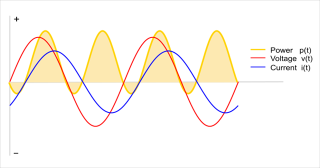
so power actually flows both ways in any non-trival situation, even if by convention we sometimes ignore it.
- Andy.
As I understand it, not just RCDs - other devices (e.g. some MCCBs) can suffer similarly, and presumably some AFDDs (with or without RCD function included) might too? There might be related problems even with simple fuse carriers - e.g. older types that leave one end of the fuse connected to the load circuit as it's being changed (but as a shock hazard rather than equipment damage, but basically the same cause - having a voltage where it wasn't expected).
I've been whittling down from an extensive list of issues that have been discussed here and elsewhere – in terms of the intended effect of this amendment and the potential pitfalls.
I was very sceptical but now I’m absolutely in favour of the substantive effect, and I’ve tried to capture that in a way which conveys some of the rationale.
But below is my current draft. I don't think I'll be adding or removing much more. My proposed Note 4 is an interesting pandora's box - I once encountered an incident where a single phase induction motor in a compressor was backfed from the pressure vessel, I think the starting capacitor allowed the windings to remain excited and it made a right mess of the DOL starter. Fortunatly it didn't make a mess of an operators hand. It should have had a non-return valve but that's another story.
[DRAFT]
Part 5 Chapter 53:
530.3.201 Selection and erection of equipment for protection, isolation, switching, control and monitoring shall take account of the conditions at each set of connection terminals when the installation is in each operating state and under single fault conditions.
Consideration shall be given to:
(i) Sets of connection terminals that may remain live after a protective device has operated.
(ii) The transient behaviour of any generating set when it is disconnected from the rest of the installation.
(iii) The prospective fault current (Ipf) that may flow through the device in the event of a fault at each set of connection terminals.
It is recommended that devices for unidirectional operation are not selected for use where bidirectional power flow is possible.
Note 1: Generating sets might remain live and their terminals may be at an abnormal voltage and/or frequency after they are disconnected.
Note 2: This does not preclude the use of unidirectional devices when it is assessed that the device is suitable for use with a particular generating set, including under single fault conditions, without impairing safety.
Note 3: Product standards as listed in Appendix 1 for RCCBs, RCBOs, circuit-breakers and AFDDs require these devices to be marked if they are unidirectional.
Note 4: Equipment which accumulates energy such as machinery with substantial kinetic energy in the inertia of their moving parts, may under fault conditions unintentionally generate electrical energy.
[/DRAFT]
We're about to take you to the IET registration website. Don't worry though, you'll be sent straight back to the community after completing the registration.
Continue to the IET registration site