Solution to Failed Zs Street Lighting Circuit.

Im currently carrying out periodic inspections on a local governments street lighting circuits and many are failing Zs tests. Not just by a little some 20/30 ohms. The circuits are all being protected by BS88-3 Fuses from 10A upto a maximum of 25A depending on the size of the circuits. 

My question is can the circuits have a second fuse inserted at a point where the Zs is acceptable.  I believe not that our only solution is to improve the reading or fit and Rccbo to give the circuits the correct disconnection times.

Thank you for any feed back
Parents
  • Thank you for the replies, the lighting circuit is supplied with a TN-C-S hydro supply and the Ze readings are well within the supply authorities values.

    As for the failing circuit itself it is aproximately 500m in total with 17 streetlighting columns equally spaced. The main issue ive had testing is the age and type of cables used in the circuit for example one span is 2.5mm solid 2 core SWA relying on the old coroded armour as the earth conductor. The next span is 4mm 2 core SWA again relying on the armour. Judging by the changing cables aswell there is evidence of underground joints although there are no records of this.  

    Continuity of the Earth conductors has been checked.

    As for the streetlighting columns, it is a mixed bag again with very old aluminium columns and steel columns however not all bonding was present.

    I was happy with voltage drop as its only 2 volts less than the supply.

    As an update ive been through the whole circuit replacing very old equipment and fitting suplimentary bonding to all the columns and cleaning up the armour where possible for a better mechanical conection and this has brought the Zs down to 5.23ohms for a 10A bs88-3 fuse.

    Now before the improved results i was asked to fit a second fuse mid way along the circuit rated lower than the circuit fuse, so for example change the circuit Fuse to a 16A bs 88 and when the Zs value became to high along the circuit, then fit a second 10A fuse to protect the rest of the circuit.

    I hope that makes sense because i dont believe this to be the correct solution.

    Sorry i have no pictures but ill try to do some sort of diagram.

    Thank you again for any help

Reply
  • Thank you for the replies, the lighting circuit is supplied with a TN-C-S hydro supply and the Ze readings are well within the supply authorities values.

    As for the failing circuit itself it is aproximately 500m in total with 17 streetlighting columns equally spaced. The main issue ive had testing is the age and type of cables used in the circuit for example one span is 2.5mm solid 2 core SWA relying on the old coroded armour as the earth conductor. The next span is 4mm 2 core SWA again relying on the armour. Judging by the changing cables aswell there is evidence of underground joints although there are no records of this.  

    Continuity of the Earth conductors has been checked.

    As for the streetlighting columns, it is a mixed bag again with very old aluminium columns and steel columns however not all bonding was present.

    I was happy with voltage drop as its only 2 volts less than the supply.

    As an update ive been through the whole circuit replacing very old equipment and fitting suplimentary bonding to all the columns and cleaning up the armour where possible for a better mechanical conection and this has brought the Zs down to 5.23ohms for a 10A bs88-3 fuse.

    Now before the improved results i was asked to fit a second fuse mid way along the circuit rated lower than the circuit fuse, so for example change the circuit Fuse to a 16A bs 88 and when the Zs value became to high along the circuit, then fit a second 10A fuse to protect the rest of the circuit.

    I hope that makes sense because i dont believe this to be the correct solution.

    Sorry i have no pictures but ill try to do some sort of diagram.

    Thank you again for any help

Children
  • Now before the improved results i was asked to fit a second fuse mid way along the circuit rated lower than the circuit fuse, so for example change the circuit Fuse to a 16A bs 88 and when the Zs value became to high along the circuit, then fit a second 10A fuse to protect the rest of the circuit.

    It would seem a reasonable approach if the c.p.c. was reliable and the high readings were just down the the length and limited c.s.a. of the conductors.  Or even a 10A fuse at the start if the loads are sufficiently low and you wanted a more conventional design. If overcurrent devices would serve, that might be preferable - adding say a 30mA RCD at the source might guarantee ADS but it may quite likely be susceptible to nuisance tripping - given the length of circuit and likely dampness (never mind number of fittings and likely protective conductor currents) - and loosing lighting unnecessarily could itself be a safety hazard. A higher rated RCD might be an option as a half-way house as it were.

    A quick google suggests R1+R2 of 4mm² 2-core SWA is in the region of 0.0125Ω/m so around 6.25Ω for 500m, plus say 0.35Ω for a PME supply, so say 6.6Ω total Ze, so your 5.23Ω figure might be plausible as representing a good metallic path (depending on quite what medley of size/lengths of cables you have). But for me the question of reliability remains. If it's likely to corrode again then you'd be back to square 1 - and an RCD wouldn't necessarily save you either as given enough time the c.p.c.s might continue to corrode until Zs was too high for even an RCD to provide ADS - or in the extreme it could rot through completely leaving the c.p.c. entirely open circuit. Each strand of SWA cable armour is normally galvanised, so if it's corroded and been cleaned, it seems likely the galvanisation has already been lost, so it would be even more susceptible to corrosion than it was originally. So for me, get the c.p.c. sorted out then everything else follows on much more nicely,

        - Andy.

  • Just to add one more thought, if you're happy the corrosion problem is just at the accessible ends of the cables, one option might be to re-make the connections and then somehow enclose it in a way that reliably excludes the moisture which is presumably the trigger for corrosion - e.g. with a resin joint or in box filled with electrical waterproofing (e.g. "magic") gel.

      - Andy.

  • Good,  it is supposed to be earthed any by the sound of it suffers from rot and grot at the glands, I presume they are not outdoor glands, and really they should have been be. In damp locations Vaseline can be used to prevent or at least slow down corrosion.

    Are you using a 'no trip' Zs meter ? If you have the option, it  may be worth trying a high current test as well and see what happens. A realistically high  fault current tends to 'kill or cure' scratchy joints, and knowing what the resistance is to a low current fault is not that helpful.

    Mike

  • I presume they are not outdoor glands

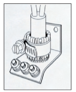
    Some of the things intended for terminating SWA in street lighting bare more of a resemblance to a jubilee clip and a short length of pipe than anything with o-rings in it... e.g. https://www.powerandcables.com/wp-content/uploads/2019/02/Central-Earth-Terminal-CET-for-Steel-Wire-Armour-SWA-Cable-Termination-of-Street-Lighting-Cables.pdf

      - Andy.

  • Nice to see them on one page with the glands. Something like that is common on the continent (well Germany at least) for armoured or braided cables as well.
    Oddly if we saw one of those, in a domestic situation like a meter box or a supply to a garage CU we'd have a fit, as the single insulated splayed cores are not inside anything and are accessible .

    However, given that some sparks don't seem able to use glands with the right size star washers , perhaps we should actually encourage more of this sort of thing rather than the current attitude of  'waste some copper, use a CPC core and assume the armour may not be really earthed' which accepts a compromise of the ADS. 

    Mike.