Neutral earth links in feeder pillars

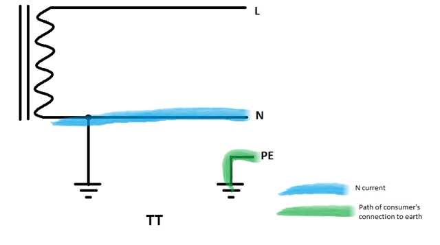
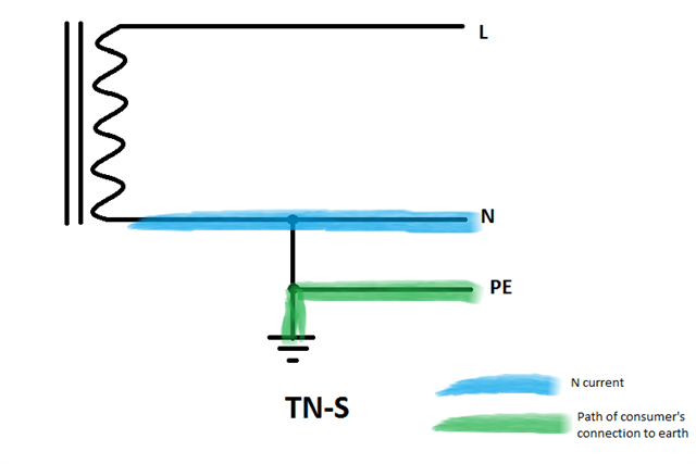
So, we have a private HV network on site that feeds feeder pillars and LV switchboards as a TN-S system.

I have multiple locations where I think there are neutral earth links that shouldn't be there, but even though it doesn't "feel" right to me, especially when I see 26 amps going down the earth conductor and only 16 amps going down the neutral in one particular place.

Example one - TP+N from TX into new feeder pillar which then feeds onto an old feeder pillar - neutral earth links in both, and they are only 2 metres away from each other.  One of these fuseways then feeds a building that has another neutral earth link in the switchpanel.

Example two - TP+N from TX into LV switchpanel (ACBs and MCCBs) which then feed two separate feeder pillars - both which have neutral earth links in them.  Although I haven't seen it myself, I am guessing that the LV switchpanel has it's own neutral earth link too.

I hope it's not correct, as I just don't see how it can be, but always willing to learn!! Slight smile

Parents
  • Are both the neutral and earth cables sized for full potential current? You maybe need just a few to be low in capacity to provide additional reasons for 'fixing' any problems. Just a thought.

  • Is this part of your on-site distribution, or consumption side ?

    I.e are any current consuming loads connected to the TNS part between the links ? 
    If not you might be marginally legally OK, even in the UK. Depending how the system was set up, a TNC distro to each building say, but in the building feeding TNS final circuits is permitted - for none consumer circuits only (DNOs do exactly that of course)
    Legality aside, it needs some serious thought to get it right, and then does not work well if the earths of different areas are cross linked,  and what you have sounds like it may be if it is diverting current through the earthing and perhaps the building superstructure which is not a good sign.

    Don't remove anything yet though - if there are high resistance links masked by the down stream ones it may make it vastly worse. If there are separate neutrals and CPCs in the feeds to the pillars/ cabinets or whatever, then the CPC and neutral continuity should both be verified, as should the presence of upstream link,  before removing the load end link and converting to TN-S, (or TN-s depending on your preference, I tend to follow a former forum contributor's convention of the small 's' load side, and the large one distribution side)

    Don't move more than one thing at a time and don't have it energised if/when you do.

    Also, related, where is the CPC earthed to terra-firma - where are whatever is acting as the system LV electrodes ?
    Mike

  • Morning, sorry, just trying to decipher the first bit.

    Each feeder pillar has TP+N plus CPC supply, so wouldn't be TN-C.  Not sure what is meant by on-site distribution or consumption side though, although it may be asking whether I believe that there is TN-C to each feeder pillar and then that's where the neutral earth link is, which I don't believe it is.

    Would definitely be eyeballing and testing each and every part before taking anything out, when it's isolated of course.

    With regards to the LV electrodes, we have a combined HV/LV earth electrode as we are not a hot site. 

  • The neutrals are bigger than the earths, not taking into account the armouring of the supply cable.  These systems have been working without issue for the last 17 years, but that doesn't mean that the earth should be carrying load current in its normal working life.

  • Well distribution cables only supply boxes doing the  ADS and perhaps metering, that in turn  supply final circuits that may have loads directly connected,. If it has a directly connected load at any point  its not "distro".

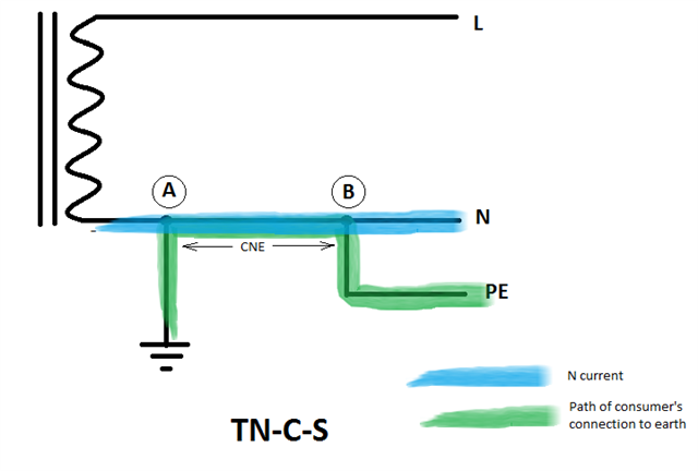
    I think what you have could perhaps be described as TN-S-C-s, as NE is first both common then separated then connected then separated again, which is not really a recognized combination in the UK unless you are operating your own distribution network ;-)

    I'm assuming you are in the UK. In much of Europe, or in AU/NZ this sort of thing would, or at least if done rightl could, be fine.

    Mike.

  • I think what you have could perhaps be described as TN-S-C-s, as NE is first both common then separated then connected then separated again, which is not really a recognized combination in the UK unless you are operating your own distribution network ;-)

    'reconnection' of N and PE is not permitted by BS 7671, and I don't think it has been at least as far back as prior to 15th Ed of the Wiring Regulations.

  • 'reconnection' of N and PE is not permitted 

    quite. But it is very common on the network operator side of the intake fuse, and in what we would now call the "building networks" of some older blocks of flats that used to be maintained by the area boards, neither of which fell/fall under the wiring regs / '7671.

    Quite sensibly, since the rule changes that turned some unsuspecting freeholders of flats into unskilled owners and operators of building networks, the distro in new blocks of flats,  is now designed and tested  to '7671, and normally with SWA or trunked cables with no additional NE bonding. 
    But, there is a lot of older stuff out there and we don't know who put this in, or when, or who they were working for and private networks can be a bit odd, to say the least.

    Mike.

  • "building networks" of some older blocks of flats that used to be maintained by the area boards, neither of which fell/fall under the wiring regs / '7671

    Although, BS 7671 is often specified for new/upgrade works on these systems ... BS 7671 does cover TN-C systems, so can be used, but TN-C-S-c-...-s isn't permitted.

  • TN-C-S-c-...-s

    Ignoring any colour coding, I guess you could deem it to be simply TN-C-S with the PEN consisting of two (or more) conductors in parallel for part(s) of the route. As long as they're not designated as separate N and PE conductors, but rather as PENs, BS 7671 wouldn't object I think. (As Mike suggests, common practice in DNO land where old 4-core + armour cables are converted to PME with "N"-armour links scattered here there any everywhere).

       - Andy.

  • cannot do that, if there is a load part way along, between links, as that makes use of the '-s' nature of things.
    Its all splitting hairs, it may or may not be illegal, its not a good approach technically, and as a country we don't like it.

    M.

  • gnoring any colour coding, I guess you could deem it to be simply TN-C-S with the PEN consisting of two (or more) conductors in parallel for part(s) of the route.

    Not really ... especially if exposed-conductive-parts, or extraneous-conductive-parts, connected to different bits of the TN-C-S-c-...-s, are simultaneously-accessible (in any combination). It's back effectively to 411.3.1.1 2nd para.

Reply
  • gnoring any colour coding, I guess you could deem it to be simply TN-C-S with the PEN consisting of two (or more) conductors in parallel for part(s) of the route.

    Not really ... especially if exposed-conductive-parts, or extraneous-conductive-parts, connected to different bits of the TN-C-S-c-...-s, are simultaneously-accessible (in any combination). It's back effectively to 411.3.1.1 2nd para.

Children
  • if there is a load part way along, between links, as that makes use of the '-s' nature of things.

    But not a problem if all the tap off points have their own N-PE links? (as the OP seems to suggest might be the case?) Even if a few don't and a "presented as TN-S" supply is tapped off mid way between links... I'm not entirely seeing what the problem is (at least any problems that wouldn't already be present in a conventional TN-C-S system with a single conductor PEN). I'll have a think... 

    especially if exposed-conductive-parts, or extraneous-conductive-parts, connected to different bits of the TN-C-S-c-...-s,

    Is that any more of a problem that adjacent installation tapped off from different positions along a conventional PME main? (I think I might have a different picture in my mind's eye, so might well be overlooking something significant...).

      - Andy.

  • But not a problem if all the tap off points have their own N-PE links? (as the OP seems to suggest might be the case?) Even if a few don't and a "presented as TN-S" supply is tapped off mid way between links... I'm not entirely seeing what the problem is

    If conditions for PME as presented in ENA Engineering Recommendation G12 are not met, then there can be excessive voltages between parts of the PEN conductor. If these are transferred by cpc's or bonding so they are simultaneously-accessible, this can be a problem. Bonding parts of the system together resolves this ... but provides its own problems through diverted neutral currents.

    Problems can be exacerbated by damp ground of the type we have in lots of the UK (but not all) ... which is why we don't often use TN-C systems here (except the TN-C portion of the system in the supply network) and why ESQCR is written as it is.

    It's worth, at this point, talking about PNB ... when used in private systems (where supplies have multiple sources with supplies from DNO at HV), this is usually really only TN-C-S on a "technicality" that the N conductor from the source can carry earth fault current back to the source, rather than actually having a PEN conductor that's intentionally used for neutral and protective provisions ... it is actually this latter "combining neutral and protective functions in the same conductor' that's actually prohibited under ESQCR.

    If you take things too literally, you could never have a generator or transformer in a private network, because there's always a neutral conductor popping out of the source for termination of the neutral conductor (and system referencing conductor where appropriate).

  • is usually really only TN-C-S on a "technicality" that the N conductor from the source can carry earth fault current back to the source

    Down that train of thought lie dragons I fear. This is the trouble of thinking in terms of earth fault loops - follow that logic and even TT should be considered TN-C in part - which cannot have been the original intention. If rather you think in terms of the path the installation has to Earth (which I think is the key issue when worrying about what can result in exposed-conductive-parts attaining a hazardous voltage relative to Earth).

    Consider...

    I think it becomes much clearer that only in a true TN-C-S system can the N current have any effect on the potential on exposed-conductive-parts, or a broken N result in earthed parts becoming live.

       - Andy.

  • I think it becomes much clearer that only in a true TN-C-S system can the N current have any effect on the potential on exposed-conductive-parts, or a broken N result in earthed parts becoming live.

    N currents having effect on touch-voltages is a good reason why TN-C-S-c-...-s is a problem.

    follow that logic and even TT should be considered TN-C in part

    Agreed

    which cannot have been the original intention

    Really? Have a look at Regulations 312.2.1.1, 312.2.2.1, which require earthing 'at the source'.

    How far from 'the source' does earthing for TN-S have to be before it is classified as "TN-C-S PNB"?

    And we know that we have have 'TN-C-S' supplies that are (to use a commonly-used, but perhaps no-longer valid term) "exported" using TT earthing arrangements (with the PME earthing terminal as "source earth" but in fact it's not necessarily earthed at source, and hence perhaps not strictly fully conformant to the "ideal" systems presented in BS 7671?

    Is "PNB" actually a thing? Capacitances and fault-current flows in broken neutral (between source and eart) situations in three-phase systems do lead to huge safety problems

  • think in terms of the path the installation has to Earth

    And we should be properly aware that "earth" (aka the planting medium) isn't a very good conductor on the cm^3 scale, even if it is good at the km^3 scale.

    We can all fall into the easy-mind trap of thinking all wires are good (zero impedance) and all Earths (chassis, bonds, etc) are even more perfect, when it's the opposite.

  • How far from 'the source' does earthing for TN-S have to be before it is classified as "TN-C-S PNB"?

    I suspect the DNO think about things in a different way - not so much in terms of lengths, but number of electrodes - if the system doesn't have multiple electrodes, it can't be PME, but N is still earthed, so it must therefore be PNB. Even on "ordinary" PME system, if you look a rural overhead installations, the 1st electrode is sometimes a whole span (a few tens of metres) away from the transformer (to keep HV and LV earthing separate).

    Is "PNB" actually a thing?

    In DNO land, certainly. It doesn't always map nicely onto BS 7671 nomenclature (TN etc) nicely though. I've seen some PNB arrangements that look like textbook TN-S to me (especially where there's only a single customer on a transformer). But I've seen other diagrams that are definitely TN-C-S (but not PME as there's only one deliberate electrode). The water seems to get muddied further by many DNOs seemingly insisting on the right to change supply arrangements in the future (perhaps not unreasonably) and so to cover themselves say that TN-S PNB customers treat the supply as if it were TN-C-S anyway (even saying "PME conditions" apply, when clearly the physics and maths of the initial setup screams otherwise). Customers with their own private transformers can make up their own minds of course.

       - Andy.

  • "Is "PNB" actually a thing?"

    Round here, SSE in Hampshire and Wiltshire it certainly is and is labelled as such on the main intake as either PNB TNS or PNB TNCS
    Usually isolated farms and campsites with one or 2 buildings and their own pole-pig transformer.

    mike

  • Usually isolated fams and campsites with one or 2 buildings and their own pole-pig transformer.

    I have seen 2 overhead cables feeding 2 cottages about 100m from the "pole pig". Definitely not TN-S, nor TT.

  • Round here, SSE in Hampshire and Wiltshire it certainly is and is labelled as such on the main intake as either PNB TNS or PNB TNCS

    Apologies for the confusion. Question was rhetorical really, I was intending to point out that PNB certainly does require special consideration due to the dangers I went on to communicate:

    Capacitances and fault-current flows in broken neutral (between source and earth) situations in three-phase systems do lead to huge safety problems

    If the neutral breaks in a single-phase part of the network, the situation will be obvious because of voltage collapse. This is not necessarily the case if the neutral break occurs in a three-phase part of the network, and in PNB systems can lead to all sorts of problems (as it can in PME systems).

  • Definitely not TN-S, nor TT.
    might be the 'almost PME' flavour of PNB, where there is one electrode and at each house N is linked over in the service head to  create  the house CPC. 
    Might also just be real PME if there are electrode wires running down the poles at more than one location. Commonly there is one at the first post that is not shared with the HV, as pole transformers are  quite often 'hot' sites, so HV and LV earths are spaced apart, and then maybe one or more nearer the load end of the LV runs.  

    It has to be said that hiking about with a pair of binoculars will reveal a lot of rural installations that are not quite as simple and clear-cut as the text book illustrations - for example neighbouring houses that are a mix of  TT and TN-something sharing the same  LV feed and so on.  It all works in practice of course but the theory hits only in a few places where it touches.
    Mike.