Neutral earth links in feeder pillars

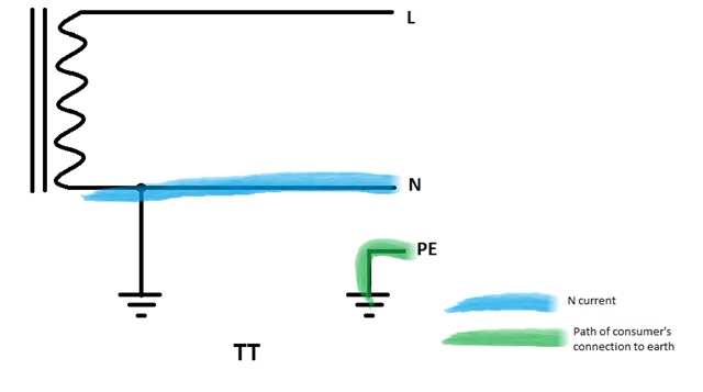
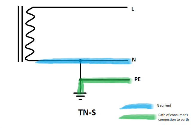
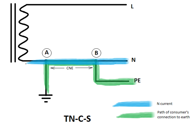
So, we have a private HV network on site that feeds feeder pillars and LV switchboards as a TN-S system.

I have multiple locations where I think there are neutral earth links that shouldn't be there, but even though it doesn't "feel" right to me, especially when I see 26 amps going down the earth conductor and only 16 amps going down the neutral in one particular place.

Example one - TP+N from TX into new feeder pillar which then feeds onto an old feeder pillar - neutral earth links in both, and they are only 2 metres away from each other.  One of these fuseways then feeds a building that has another neutral earth link in the switchpanel.

Example two - TP+N from TX into LV switchpanel (ACBs and MCCBs) which then feed two separate feeder pillars - both which have neutral earth links in them.  Although I haven't seen it myself, I am guessing that the LV switchpanel has it's own neutral earth link too.

I hope it's not correct, as I just don't see how it can be, but always willing to learn!! Slight smile

Parents
  • Are both the neutral and earth cables sized for full potential current? You maybe need just a few to be low in capacity to provide additional reasons for 'fixing' any problems. Just a thought.

  • The neutrals are bigger than the earths, not taking into account the armouring of the supply cable.  These systems have been working without issue for the last 17 years, but that doesn't mean that the earth should be carrying load current in its normal working life.

  • Well distribution cables only supply boxes doing the  ADS and perhaps metering, that in turn  supply final circuits that may have loads directly connected,. If it has a directly connected load at any point  its not "distro".

    I think what you have could perhaps be described as TN-S-C-s, as NE is first both common then separated then connected then separated again, which is not really a recognized combination in the UK unless you are operating your own distribution network ;-)

    I'm assuming you are in the UK. In much of Europe, or in AU/NZ this sort of thing would, or at least if done rightl could, be fine.

    Mike.

  • I think what you have could perhaps be described as TN-S-C-s, as NE is first both common then separated then connected then separated again, which is not really a recognized combination in the UK unless you are operating your own distribution network ;-)

    'reconnection' of N and PE is not permitted by BS 7671, and I don't think it has been at least as far back as prior to 15th Ed of the Wiring Regulations.

  • 'reconnection' of N and PE is not permitted 

    quite. But it is very common on the network operator side of the intake fuse, and in what we would now call the "building networks" of some older blocks of flats that used to be maintained by the area boards, neither of which fell/fall under the wiring regs / '7671.

    Quite sensibly, since the rule changes that turned some unsuspecting freeholders of flats into unskilled owners and operators of building networks, the distro in new blocks of flats,  is now designed and tested  to '7671, and normally with SWA or trunked cables with no additional NE bonding. 
    But, there is a lot of older stuff out there and we don't know who put this in, or when, or who they were working for and private networks can be a bit odd, to say the least.

    Mike.

  • "building networks" of some older blocks of flats that used to be maintained by the area boards, neither of which fell/fall under the wiring regs / '7671

    Although, BS 7671 is often specified for new/upgrade works on these systems ... BS 7671 does cover TN-C systems, so can be used, but TN-C-S-c-...-s isn't permitted.

  • TN-C-S-c-...-s

    Ignoring any colour coding, I guess you could deem it to be simply TN-C-S with the PEN consisting of two (or more) conductors in parallel for part(s) of the route. As long as they're not designated as separate N and PE conductors, but rather as PENs, BS 7671 wouldn't object I think. (As Mike suggests, common practice in DNO land where old 4-core + armour cables are converted to PME with "N"-armour links scattered here there any everywhere).

       - Andy.

  • cannot do that, if there is a load part way along, between links, as that makes use of the '-s' nature of things.
    Its all splitting hairs, it may or may not be illegal, its not a good approach technically, and as a country we don't like it.

    M.

  • gnoring any colour coding, I guess you could deem it to be simply TN-C-S with the PEN consisting of two (or more) conductors in parallel for part(s) of the route.

    Not really ... especially if exposed-conductive-parts, or extraneous-conductive-parts, connected to different bits of the TN-C-S-c-...-s, are simultaneously-accessible (in any combination). It's back effectively to 411.3.1.1 2nd para.

  • if there is a load part way along, between links, as that makes use of the '-s' nature of things.

    But not a problem if all the tap off points have their own N-PE links? (as the OP seems to suggest might be the case?) Even if a few don't and a "presented as TN-S" supply is tapped off mid way between links... I'm not entirely seeing what the problem is (at least any problems that wouldn't already be present in a conventional TN-C-S system with a single conductor PEN). I'll have a think... 

    especially if exposed-conductive-parts, or extraneous-conductive-parts, connected to different bits of the TN-C-S-c-...-s,

    Is that any more of a problem that adjacent installation tapped off from different positions along a conventional PME main? (I think I might have a different picture in my mind's eye, so might well be overlooking something significant...).

      - Andy.

  • But not a problem if all the tap off points have their own N-PE links? (as the OP seems to suggest might be the case?) Even if a few don't and a "presented as TN-S" supply is tapped off mid way between links... I'm not entirely seeing what the problem is

    If conditions for PME as presented in ENA Engineering Recommendation G12 are not met, then there can be excessive voltages between parts of the PEN conductor. If these are transferred by cpc's or bonding so they are simultaneously-accessible, this can be a problem. Bonding parts of the system together resolves this ... but provides its own problems through diverted neutral currents.

    Problems can be exacerbated by damp ground of the type we have in lots of the UK (but not all) ... which is why we don't often use TN-C systems here (except the TN-C portion of the system in the supply network) and why ESQCR is written as it is.

    It's worth, at this point, talking about PNB ... when used in private systems (where supplies have multiple sources with supplies from DNO at HV), this is usually really only TN-C-S on a "technicality" that the N conductor from the source can carry earth fault current back to the source, rather than actually having a PEN conductor that's intentionally used for neutral and protective provisions ... it is actually this latter "combining neutral and protective functions in the same conductor' that's actually prohibited under ESQCR.

    If you take things too literally, you could never have a generator or transformer in a private network, because there's always a neutral conductor popping out of the source for termination of the neutral conductor (and system referencing conductor where appropriate).

Reply
  • But not a problem if all the tap off points have their own N-PE links? (as the OP seems to suggest might be the case?) Even if a few don't and a "presented as TN-S" supply is tapped off mid way between links... I'm not entirely seeing what the problem is

    If conditions for PME as presented in ENA Engineering Recommendation G12 are not met, then there can be excessive voltages between parts of the PEN conductor. If these are transferred by cpc's or bonding so they are simultaneously-accessible, this can be a problem. Bonding parts of the system together resolves this ... but provides its own problems through diverted neutral currents.

    Problems can be exacerbated by damp ground of the type we have in lots of the UK (but not all) ... which is why we don't often use TN-C systems here (except the TN-C portion of the system in the supply network) and why ESQCR is written as it is.

    It's worth, at this point, talking about PNB ... when used in private systems (where supplies have multiple sources with supplies from DNO at HV), this is usually really only TN-C-S on a "technicality" that the N conductor from the source can carry earth fault current back to the source, rather than actually having a PEN conductor that's intentionally used for neutral and protective provisions ... it is actually this latter "combining neutral and protective functions in the same conductor' that's actually prohibited under ESQCR.

    If you take things too literally, you could never have a generator or transformer in a private network, because there's always a neutral conductor popping out of the source for termination of the neutral conductor (and system referencing conductor where appropriate).

Children
No Data