Hi All. I'm a medically retired electrician with additional strings to the bow throughout my career. From contracting on commercial electrical installations to building/designing large industrial containerised generators to managing landfill gas generator installations and finishing at building maintenance engineer covering alot of variable skills with HVAC and BMS.
I try to keep the mind busy and do what I can.
Appreciate your viewing my question I'll try to be as descriptive as possible.
My home is TN-C-S supply with no extraneous parts ( water supply is plastic pipe and no gas supply).
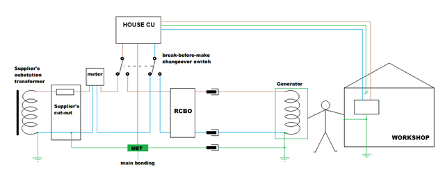
Approximately 5 years ago I installed a large metal garage/workshop 7.5m by 4.5m(concrete floor with metal box section frame bolted to the concrete pad)
I supplied the garage with a 6mm armoured via 30ma RCD and 40amp MCB ,armour being connected to house distribution board and isolated at the garage termination so as not to export the earth as per regulation,I installed 2m deep electrode and additional 1m deep electrode both wired back to garage DB. So in effect garage is on a TT system.
The house distribution boards (8 way mem bs88 and 4 way mem2000 RCD mcb) I want to change out for 1 large regulation DB , one in looking at is MK dual 100amp 30ma isolator with type 2 SPD rest populated with mcb's.
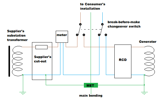
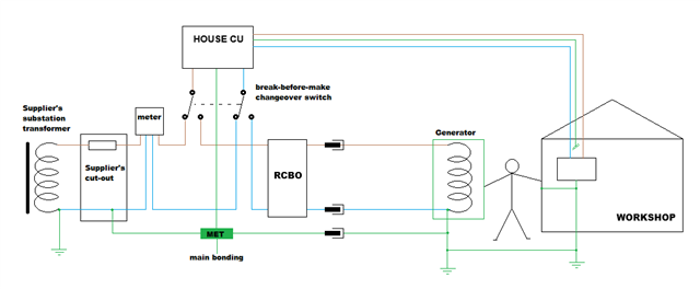
To the nub of my question. I want to install back up generator (7.5kva peak 6.25kva constant)which will be sited out the back of the metal garage( outside garage building not inside)some approx 12m from house. I'll give you my thoughts on what I'm thinking of installation to ensure complete separation from incoming mains supply to remove chance of any back feed especially under fault condition.
1. Install a single phase 32amp incomer socket ( will be supplied from generator in event of outage)to the exterior of house.
2.Wired back to a 20amp double pole rcbo enclosure in distribution cupboard.
3.From rcbo into a manual 3 pole transfer switch.
4.The network supply wired the manual 3 pole transfer switch then from transfer switch to new distribution board (dB).
5. The generator chassis will be connected to garage earth electrodes when in use.
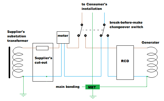
6.. 3 pole manual transfer switch? My thinking is to switch L. N. and the earth.
My thinking on this: when mains is in use garage supply has isolated earth DB side connected only as previously discussed to protect cable/circuit going to garage rest of house still using supplier earth path .
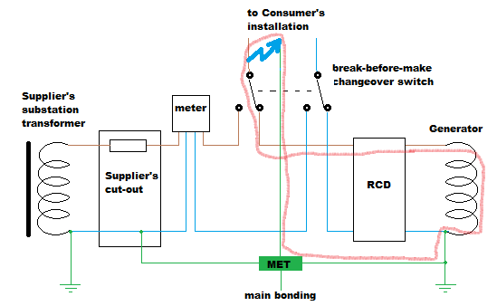
When generator supply is used the whole installation house including garage would be effectively TT system this way no chance of back feed to the supplier network including under fault conditions from my/consumer end giving earthing is also switched at the manual transfer switch, i
Q.1.is this 3 pole manual transfer idea (switching earths) idiotic/unnecessary/ not advisable ?
Q. 2. Should I include a type 1 SPD to the 20amp 30ma generator supply enclosure inside distribution cupboard given large metal shed and lighting strikes ?
Sorry for long winded pre log just trying to ensure you've all the information needed. Would be grateful for your thoughts and indeed advice.