Could you please confirm whether clause 431.1.1 (iii) in BS 7671 is accurate and up to date?

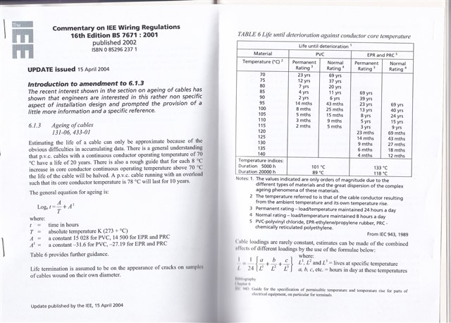
As per the requirements of BS 7671, a circuit breaker may take up to one hour to trip when subjected to a current of approximately 1.45 times its rated current. In such cases, we would like to clarify whether the associated cable is also designed to withstand 1.45 times its continuous current-carrying capacity for the same duration without degradation or thermal damage.

Is this aspect covered in any cable standards (such as BS 6004, IEC 60287, or IEC 60364) or specified in cable manufacturer datasheets?

We seek clarification on whether:

  • The cable’s short-term thermal endurance aligns with the breaker’s tripping characteristics.

  • Manufacturers consider this 1.45 × In scenario when defining safe operational limits.

Any references or guidelines from standards or datasheets that confirm the cable's ability to tolerate such overloads for a limited duration would be helpful.

  • Got to say, excellent information from GK and Mike as usual! Many thanks!

  • I suspect that some confusion is coming from texts like this one.

    BS 3036 semi-enclosed fuses cannot be relied upon to operate within 4 hours at 1.45 times the nominal
    current of the fuse element.

    From https://electrical.theiet.org/media/1611/semi-enclosed-fuses.pdf

    But this is firmly in the 'may or may not' blow grey area. In effect depending rather on the holder design, and how much heat can soak out of the wire, "30A" fuse wire will carry 30A for ever, but may or may not also carry 40 odd amps almost for ever as well. The only sure fire thing is that within 2 hours at 60A it really should have let go, but it may well do that a lot faster.
    The problem with rewireable fuses is their inherent lack of consistency, and even for the same model of holder, being dependant on how the wire was fitted and perhaps how much it was abused at the ends.
    The trick is not to rely on rewireable fuse for anything that really needs close protection - and most things don't.

    Mike.

  • Agreed, but I thought it was the co-ordination with cable characteristics (so the cable remains "protected" to some reasonable degree) that the OP was asking about (at least that was what I was attempting to answer).

    Which is why I didn't attempt to answer directly where that value came from earlier. The issue is that this has now been raised.

    The cable side of things is subtly different to the 1.45 side of things ... although the two are related, the 1.45 relates to the likelihood the fuse will operate at some given time.

  • It's actually modern protective device standards, a property of the fuse not the cable being protected.

    Agreed, but I thought it was the co-ordination with cable characteristics (so the cable remains "protected" to some reasonable degree) that the OP was asking about (at least that was what I was attempting to answer).

      - Andy.

  • On what basis was this factor of 1.45 established?

    It's actually modern protective device standards, a property of the fuse not the cable being protected.

  • It's simpler than 'calculating' ... Clause 7 of BS 3036 provides the answer:

    So, to convert the fusing factor of a modern device (1.45) to 2, uses a factor of 0.725 (or, 1.45 ÷ 0.725 = 2)

    I understand the derivation of the correction factor of 0.725 as it comes from the declared fusing factor of a 3036 fuse of 2*In at a time of 4 hours thus when applied to the formula in indent (iii), Iz>In/0.725.  

    The time for the fusing factor test according to BS 3036 is not 4 hours, but varies up to 2 hours according to Table 5 of the standard:

    Not that it makes a lot of difference when you look at the time-current curves ... 'calculated from lookup' values of 1.7 ish upwards towards the limit of 2 are seen if you were to use the graphs. Of course, we must consider that the actual fuse wire used will have variations. The time-current characteristics are captioned in BS 3036 as 'typical'.

  • Sorry to jump on the back of this but can I just ask about the effect of indent (iii) on the 3036 fuse? I understand the derivation of the correction factor of 0.725 as it comes from the declared fusing factor of a 3036 fuse of 2*In at a time of 4 hours thus when applied to the formula in indent (iii), Iz>In/0.725.  

    However, referring to Appendix 3 for 5A,15A and 30A 3036 fuses, the value I2 seems to be as good as a similarly rated BS88-2 or 88-3 fuse . I2 for other In values of 20A, 45A and 100A 3036 fuses do seem to have a much extended I2 time. 

    So is the 0.725 correction factor applicable to some, but not all, 3036 fuses?

  • On what basis was this factor of 1.45 established?

    I think it goes back a long way. If you look though the older versions of the wiring regs (long before they became BS 7671) they contained what was in effect the specification and test procedures for cables - only in more recent decades have such things been split out into specific cable standards.

    As others have said, 1.45 is probably down to 'experience and investigation' rather than any particular calculation. The concept of allowing conductors to run "too hot" for a limited time isn't unique to this situation though - during faults we allow conductors to get really very hot (have a look at the "final temperature" row on table 43.1 in BS 7671 for one example). The point is that cables don't suddenly self destruct or catch fire the moment they're overloaded, but rather they run rather warmer and the insulation degrades rather faster that it would under normal conditions - but given that in many situations insulation will be good for 70 years or more, a few events that perhaps knock a few months off the lifespan are likely to be acceptable.

       - Andy.

  • How long is a piece of string?
    Or in this case, how small is, "small"; and what amounts to a, "long duration"?

    It need not be quite as imprecise as it at first seems; although it is well hidden. Once can look at the adabatic curves of cable current handling, and the constant current ratings and look at the intersection. The answer is that the time for a cable to reach equilibrium in free air case for most common domestic cables is a few minutes.

    The second aspect is my how much the temperature rating of a cable can be exceeded, and what impact this has on the life of the insulation.

    You  can drop an offcut of cable into your mates cup of tea, and despite being well over 70c, the cable does not melt away like butter, it just gets a bit extra flexible.

    While it has now disappeared from the IET website, way back in 2004. it contained  this table . While assuming all PVC is created equal is rather dodgy, it does allow some estimation of the life shortening effect of overheating - and as temperature rise is generally proportional to the square of current, also tolerance to overloads (a current increase of 1.41 times will at worst double the temperature rise, perhaps less where convection cooling occurs and air moves faster with rising temperature). In summary a  hour or two at up to  perhaps 110C for a cable designed for operation of many decades at 70C is not likely to hurt it.
    The corollary, is that by designing things that run cool, they will probably outlive the building, let alone the installer.


    regards Mike.

  • Hence, also the requirement of Regulation 433.1 'Every circuit shall be designed so that small overload of long duration is unlikely to occur'.

    How long is a piece of string?

    Or in this case, how small is, "small"; and what amounts to a, "long duration"?

    Clearly they are inversely related, but a "small" overload could be 45% (but if your bank made an error of 45%, it would hardly be small). I regularly overload a BS 1363 socket when I turn on my toaster and kettle each morning, but 3 minutes is hardly a "long duration".

    Back to the OP, I have always assumed that if you take the tables in Appendix 4, the CCC takes into account that there could be a small overload of long duration, but I may be wrong.

    So, Table 4D2A, a 6 mm² 2-core cable installed according to reference method A should have a 32 A MCB (maximum). Just as the MCB will tolerate 46 A for a long duration, so will the cable.