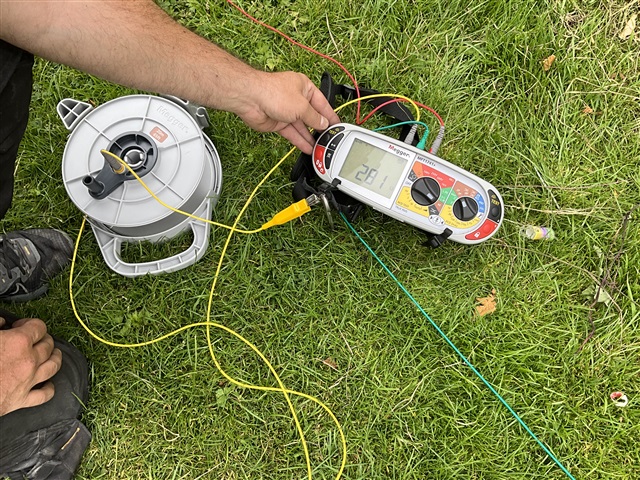
This is the resistance (281 ohms) of the earth electrode connecting star point and frame of a stand alone TPN gen set. It was one of 15 used at a recent outdoor festival. I do appreciate the desire to keep the resistance within the norms usually applied, say around 20 ohms, but I don’t think there is anything in BS7671 that puts numbers on a TN system. I am not looking to debate the merits of such earthing or how this value could be reduced. I guess my question is more concerned about the value of earth resistance that the “T” in TN-S remains legitimate as far as 7671 is concerned. Is it solely related to some value that will ensure RCD protection will operate?