Installation Reference Method B - Correct derating method question

Hi,

I am having some trouble confirming how to derate a cable correctly.  The current install is a 10mm thermosetting multicore (3 copper core 400V, SWA as earth) from dist board to UPS. There is a 63A BS88-2 gG fuse protecting the cable. Our calculations for the existing plant utilise 512.1.5 - where the cables are run to 70°C, so all cables are classed as thermoplastics, in order to negate all existing equipment checks on circuits affected by the upgrades.

Using table 4D4A, the best-case scenario described above is the cable is capable of 62A (ref. method E), but is protected by a 63A fuse. So we know we need to do something as this is before applying grouping & installation method derating factors.

The cable is a 15m run, on perforated tray & under suspended floor (again on perforated tray) bunched with other cabling (grouped as 8).

With reference to table 4A2, #47 installation method seems suitable, which defines the installation method as B.

Next I go to Table 4C1, row 1, grouped as 8. This gives a derating factor of 0.52.

What I am unclear on, is what do I apply the derating factor to? I assume it is the 62A as noted above, meaning the cable should be derated to 32.24A in this scenario. Is this correct, or is there a different value I should be using to apply the derating factor to?

Once I understand this, I can move on to the solution (load assessments to determine if the best solution is to increase the cable size, or reduce the fuse size (or both)).

Appreciate any clarification on this.

Regards, James
Parents
  • Without going into detail, it looks like you have established Iz, which can be used on a trial and error basis to arrive at a case with a ccc that meets, I assume, overload requirements. A better method might be to find the minimum acceptable ccc by dividing your correction factors into In and select It on that basis.

    Can you not get rid of the grouping element? Grouping correction factors can be punitive to any cable design calculation. Along with thermal insulation, grouping should be avoided.

    Having said that, there are dispensations to be had for grouping if certain parameters are met.

Reply
  • Without going into detail, it looks like you have established Iz, which can be used on a trial and error basis to arrive at a case with a ccc that meets, I assume, overload requirements. A better method might be to find the minimum acceptable ccc by dividing your correction factors into In and select It on that basis.

    Can you not get rid of the grouping element? Grouping correction factors can be punitive to any cable design calculation. Along with thermal insulation, grouping should be avoided.

    Having said that, there are dispensations to be had for grouping if certain parameters are met.

Children
  • Thanks for the reply.

    I agree and the aim is to determine It, and apply the appropriate derating factors to It, to derive Iz. We are able to modify the fuse, cable size (or both) in line with latest regs to achieve Iz>In>Ib.

    Sadly this is a legacy install servicing equipment which requires minimum downtime, and there is little apatite to modify the existing installation where at at all possible - so we are stuck with the onerous grouping factor.

  • The fuse is 63A, I presume the load is less ? How much less? 
    The actual heating will of course be that caused by the current that flows, not by  the fuse rating, maybe the load never reaches the fuse rating or only for short duration with lots of cool-down time in between. Are the grouped cables also running hard, or only lightly loaded ? 

    If the legacy installation is showing no signs of running hot or evidence of other distress, why the imperative to do anything in a hurry, other than put it on a regular watch? 

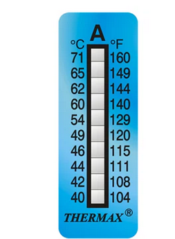
    Peak reading (non-reversible) temperature stickers can be a great friend in a case like this, as they can be put in the tight spots where air flow is restricted and other cables are close, and after a few weeks or months, can be re-inspected.

    Then you have the hard irrefutable evidence you need, to either say "sorry chaps we really must up-size this cable' or 'this is not  ideal but in practice there is no issue' and you are not left guessing if there may be a problem ahead or not.

    The tables in the regs are really only a guide, and necessarily have to err on the safe side, but as you have the actual installation, you may as well measure it.


    Mike.

    PS 
    There are a few makers of things like this - self adhesive and readily available with various nos of steps and step spacing. The grey boxes change colour to a blue/black if that 'high tide' temperature  has been exceeded.

    We sometimes build them into products, so we know if the customer returns it under warranty if they have been reckless and overloaded it in some way, or if it has been looked after, and as our instructions in a well ventilated space and and kept clean etc.
    We often put two side by side one for 'normal operation' - so we see it reached 50C inside, and another for 'you must be joking' that goes to 120C or so.. for those more intense ' you broke it ' type customer discussions. 

    Don't carry the low temperature ones in your pocket or leave them on the dashboard in the car on a hot day...