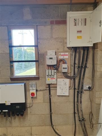
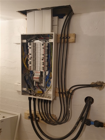
I have two 35mm 3 core submains, 70m long, running from a garage to house. on a 63A, C curve MCB. (very big house and grounds)
Armour of each is equivalent to about 9.25mm, just below the 10mm I need for bonding
Supply is 100A 3 phase, with 2 phases going to the house, 3rd to heat a pool.
One submain is going to the main house CU.
I want to take the second submain to a seperate CU for two EV chargers, putting the EV chargers on the main board is likely to take max load over 63A, can't increase the breaker due to voltage drop and I already have voltage drop concerns with the EV chargers. Implementing load management on the EV chargers is challenging because the previous electrician didn't include a data cable in the supply running through a roof and under a path.
To achieve the 10mm minimum CSA for bonding can I connect a 10mm earth between the existing and new EV CU at the house end and then consider the csa of the earth connection to be 9.25 * 2 = 18.5. In my mind it's ok, specially as 9.5 is already very close to the 10mm required?
Anything else I need to think about.
Bit more background
At 63A my voltage drop on the submain is 4.85V, at 32A it would be 2.46V. assuming Max VD for a EV charger is 3%, 6.9V. Running the second submain at 32A gives me far more flexibility. I am also dealing with a 50m cable run to one of the EV chargers. Will probably use 15m of 6mm already installed followed by 10mm for the remainder of the run.
House is in a rural location but very close to local pole mounted transformer, so hopefully voltage is reasonably stable. But having had a lot of issues with voltage variation in rural locations i am always a bit nervous about it, certainly don't want any opportunity for the DNO to point a finger at me if there are voltage issues.

