MCB surge current/device calculations

I have searched and found some similar threads on this topic, which give me some guidance - most of which says there's no definitive way to assess this, but if the learned community here can check my thinking that would be helpful.

We are providing some LED fitting drivers from ETC to the electrical contractor on a theatre project.  These are DMX controlled, and have a maintained (externally backed-up) supply connection and a sense connection.  If the supply at the sense connection fails they force the output to full brightness - but still fed from the maintained supply.  There is no local battery.

The contractor has asked how many of these could be put on a 10A Type B or type C MCB (let's assume to IEC 60947 as this is not a domestic environment).  Let's also assume we are looking to avoid the breaker tripping due to surge currents on switch-on or reset.  The manufacturer states that the inrush current is 27A within the first half cycle, 

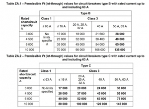
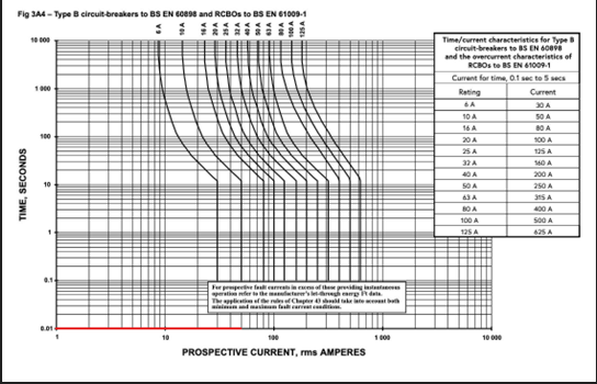
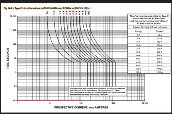
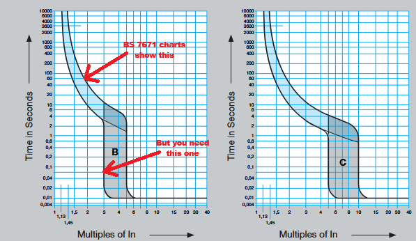
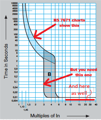
A type B MCB will fast trip at 3-5x In, and a Type C will fast trip at 5-10x In.  If we take the lower end of these figures to 'guarantee' no tripping, then we would be limited to an inrush current of 30A (1 driver) for a type B and 50A (2 drivers) for a type C.  This is just by my simplistic maths, and assumes that the inrush lasts long enough (10ms or so) for the breaker to trip.  We don't have a current-time curve from the manufacturer although we have asked for it, and also for their assessment of the number of drivers that could be put on each MCB type.

I'm sure I'm missing something here - possibly more detail on the time component.  if the inrush is 'very short' how 'short' would it need to be for the breaker not to really care about it?  What else am I missing in the simple view I'm taking?

Thanks in advance.

Jason.

  • The other thing that may be easier is for the lamp manufacturer to tell you the value of the (flat) capacitor that gets dropped across the mains and has to charge suddenly, perhaps to over 300V, if the switch on moment is near the top of the sine wave.

    We an then pretend htat the curret that flows is a rectange of constant current rather than something that tails off as the capacitor fills, to get an under estimate of the time, but an over estimate of the I2C, which you can compare to the breaker let through to give an upper bound.

    This is not precise, but it will be within a factor of two or so, do realise it is one of those 'pretend the horse is a sphere' type analyses and should be treated as that.

    This is effecively an amount of charge that needs to be transferred, and will try to do so at current set by the (generally very low)  circuit impedance.

    a 100uF capacitor charging at 30Amps, for example, reaches a 300V charge when I*t =C*V = 300* 100E-6 = 3E-2C 

    so in 3E-2/30= 1 millisecond.
    now if we look at the I2t of that rectangular current burst.

    30A*30A * 1E-3 = 0.9 joules per ohm.

    Consider that the highest permitted let-though of even a small MCB is a ~ 15 thousand times that the lowest no trip let through is likely to be some thousand or they could have made the limit lower.

    But you may have a lot more than 100uF in several LED power supplies in parallel.

    Mike

  • I could be way off on my thinking, but it has got my interest so here is my take.

    27A @50Hz/2 à (1/50Hz)/2=0.01s

    Appling this to the below I think with a with a type A only 1No. driver can be accommodated but with a type B you could get 3No.


  • Beware of the BS 7671 charts/tables - they're designed to be helpful when you're arranging things to ensure reliable disconnection (e.g. for ADS) - e.g. for B type MCBs they only show the 5x side of the "envelope". To ensure things reliably don't trip you need the lower edge of the envelope (e.g. 3x for B-types) instead .. which gives you rather smaller results.

    e.g. From one manufacturer (there's just one curve for all rating of MCB, as the currents have all been divided by the rating, In):

    That said, as Mike suggested, it's not so much the maximum size of the current pulse that counts, so much as its average up to the point the MCB might de-latch (which can be significantly before the device actually opens - as moving contacts takes time).

       - Andy.

  • The likely speed  is rather off the charted region and in as it used to say on the old pirate maps 'here be dragons' territory. 10ms is really ages for electronics - time to load and run a short program on a microcontroller let alone just charge a capacitor. Equally no MCB on earth is going to even twitch, let alone switch, in less than hundreds of microseconds at any current possible. (a fuse might explode though)
    Mike

  • Thanks all,

    I had noticed the 'lower end' curves, and if we use those with the simplified maths we don't get to put many drivers on an MCB.

    On pressing the manufacturer, they decided their data sheet was wrong and the inrush is 15A and not 27A, so on the very simple maths (B10 x 3 ->30A trip -> 2 drivers; C10 x 5 -> 50A trip -> 3 drivers).

    The manufacturer is attempting to get a current-time curve from their PSU manufacturer so we'll see if that gives us more information on the time component.

    Jason.

  • If you are waiting for them, it may be faster if you have a breaker and some fittings available to try it, adding units to the point of trouble, and then say halving that no. Or adding inrush protection, so you know it is under your control. In the past have used these in small metal box on ceramic choc block* to define the cold inrush of problematic equipment. It only adds a couple of ohms when cold, but the effect of depressing and spreading the inrush current is remarkable. I think on the last 16A circuit I did I had two SG420 in series, to give ~ 4 ohms cold, so even in to dead flat, maximum 60A inrush, and a touch under 50 milli-ohms hot. (that model will take a oneshot surge of 250Joules each per start up - and 1/2.C.V^2 can be compared to that, or 1/2.I^2.L for transformers and motors)
    Be aware that on cold test, they mess with the R1+ R2 results, and rather like a dimmer or similar, that needs factoring out of the design. RCDs are your friend there! 
    Mike.
    * needs to be ceramic - they run uncomfortably  hot for long term use with polythene or polypropylene terminals.

  • Thanks Mike.

    They are interesting looking little devices.  I'll hold that information in reserve if the electrical contractor is still struggling.

    I'll also leave them to the empirical tinkering (I'm a great believer in that approach) if they feel the need to do so.

    Thanks again for the detailed advice.

    Jason.

  • The contractor has asked how many of these could be put on a 10A Type B or type C MCB

    zero-volt switching and "staggered start" timers, are also used to help mitigate inrush currents.

    You'd also want to consider the inrush effect on sub-mains/distribution circuits?

  • Thanks Graham.

    I'll leave the electrical contractor to worry about that!

  • I'll leave the electrical contractor to worry about that!

    Surely, you mean 'designer' of the installation?

    Being  a bit devilish here, but it's not just the "installer" ("contractor") ... I'm wondering who is the "designer"?