Overcurrent protection - Combined fuses and contactors

Hi all,

A Client has recieved delivery of equipment incorporating a battery which is connected to a DC load by cabling. The cabling is protected by overcurrent protection in the equipment comprising aR fuses and contactors which are controlled by a proprietary arrangement with current monitoring, including what amounts to a definite time overcurrent function for overload protection.

The concern is that the aR fuses are (by designation and design) not full-range, so provide fault protection only, while the contactors are only rated by the component OEM to break a certain overload current... and the fuse cut-off as for guaranteed performance is greater than the contactor break rating*. This leaves a small gap (circa 2% of the prospective fault current, or 10% of the contactor overload break rating) between the overload and fault protection functions where neither device is guaranteed to operate.

A side-note is that it is has not yet been confirmed to me that the overload trip is disabled above the contactor's break rating, so while the fuse will be available to act, up to double its rating the contactor might make the first attempt.

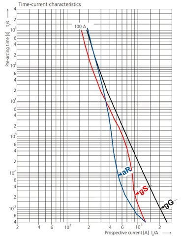
The equipment manufacturer has stated that they've carried out a test - details not provided - in which the fuse did operate in roughly half the I-t pre-arcing chart time (!) and the contactor survived (not sure if it operated) so everything's golden. The equipment does come with a third-party certificate of conformity to an appropriate IEC product standard. The standard does require the manufacturer to consider all external overcurrents and to declare any particular requirements for overload or fault protection, but from what I can tell the standard doesn't actually test for mid-range overcurrents, just small overloads and golden spanners.

My worry is that, irrespective of whether it's okay for the product/equpment standard, for the cable there may be a lack of compliance with BS7671 §430.3 and §435.2, insofar as there is a possibility that a high impedance fault, or an exceptionally bad day for the load controller, may give rise to overcurrent which neither overcurrent device is rated to break.

It would have been possible for the manufacturer to specify components with sufficient overlap (they exist), but retrospectively changing may not be easy not least as it might change its characteristics.

Questions:

  1. Am I right to pursue this gap in overcurrent protection for the cable or is the fact that its protection comes from within a piece of equipment to an IEC standard sufficient to meet the equivalency requirements of 533.1.1?
  2. What effect, in reality, might an attempt to break the over-overcurrent on this magnitude have on the contactor? Is it concievable that it might fail to break the current at all and/or fail disruptively, break it but need replacement afterwards, or is this one of those scenarios where safety tolerances mean that it will probably achieve the job just without as much margin as we'd like?

Jam

*The break rating is roughly 5x the nominal load rating

  • My worry is that, irrespective of whether it's okay for the product/equpment standard, for the cable there may be a lack of compliance with BS7671 §430.3 and §435.2, insofar as there is a possibility that a high impedance fault, or an exceptionally bad day for the load controller, may give rise to overcurrent which neither overcurrent device is rated to break.

    If this is a place of work, Regulation 11 of the Electricity at Work Regulations is a more pressing issue than a discussion on conformity to BS 7671.

    If it is known the equipment is intended for the workplace, the supplier and/or manufacturer have an obligation under legislation to provide adequate information to ensure the equipment can be installed safely, and to maintain safety during use.

    So, I would ask the manufacturer, importer or supplier of the equipment what they recommend in line with the H&S@W etc Act and the Consumer Protection Act.

  • Agreed but it is probably easier contractually if nothing else to point to the right bit of '7671 or other IEC/EN/BS standards, particularly since the manufacturer and supplier are both overseas.

  • Am I right to pursue this gap in overcurrent protection for the cable

    I'll just make the observation that it's common practice to protect a, say, 20A cable with a 32A OPD (unfused spur from a ring, for example) and such arrangements are usually considered to comply with BS 7671. So the assumption that all faults may be assumed to have a negligible impedance isn't that outlandish (if perhaps a slight oversimplification). 

      - Andy.

  • Good point. Thanks for the reality check.Thumbsup

    Will go away and remind myself of the basis for why that arrangement is considered okay (custom and practice with diversity if I recall, plus the 13A plug fuses) and see how much of the logic is applicable here.

  • and we accept that there is a small risk of shortening the cable life if a sustained overload occurs that is not enough to operate the MCB.. 
    I premium the fuse or breaker will always operate, but maybe not as smartly as you might like, and the breaker may need replacement if the fuse takes its time ?
    Mike

  • Because they're only partial range aR fuses, below the I2a minimum value of the breaking range the manufacturer will not guarantee that the fuse will clear the overcurrent at all. For HV fuses there is the risk that the link might melt but not sufficiently smartly to avoid prolonged arcing resulting in catastrophic fuse rupture. In this case the voltage is >1kVdc and substantial current so this may also be the case here, although it's only just outside the range so it may just fail to clear in reasonable time and get hot in the meantime.

  • Would and RCBO upstream help possibly?

  • Thanks but an earth fault device wouldn't see an overcurrent (Pos-Neg) issue.

  • Nor are there many DC RCBOs about...

       - Andy.

  • Oh.
    Clearly the breaker is undersized. Or the fuse is oversized... 
    Struggling to visualize the problem and feeling in need of a quick refresher, I've just had a quick look at the Eton fuse FAQ (https://www.eaton.com/content/dam/eaton/products/electrical-circuit-protection/fuses/bussmann-series-high-speed-fuses/bus-ele-an-10507-hsf.pdf )

    Ignore my earlier response. 
    I now have the below graphical understanding  of the issue, and why the gG general fuse is often seen on the drawings paired with a similar rated aR one - the general fuse "fills in the gap" for modest overloads of longer durations. Something new learnt every day.

    There used to be so called 'semiconductor' fuses back in the last century that were not made of semiconductor, but were designed to protect transistors and similar, that also had very fast energy limiting breaking responses but like the Ar were also pretty useless at 'close' protection.


    The other complication is that with DC, when you dont have zero-crossings the arc tends to persist longer, especially with inductive loads.

    I suspect that the designers of the kit might have failed to realise there was more to it than at first appears.

    I think an additional slower blow, but closer protection fuse may be in order to ensure all gaps are filled. It's not quite the same as the unfused spur case.
    Mike.