Current transformers

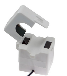
In distribution subs they have thermal ammeters I think they have a 30 minute warm up time so they don't get hammered by large starting currents or faults. I think I'm right in saying that the meters are switched out if circuit forr most of the time I'm you'd you can't leave CTs open circuited so do they just put a resistor across  the CTs in are the meters usually left in circuit. 

Parents
  • Also worth considering that, without a resistor or short at the current transformer, the voltage will not be maintained in the SELV range.

    You can buy current transformers that are guaranteed SELV, but they are very expensive.

    For other current transformers, these need to be treated as FELV at least, if not LV, and preferably go in an enclosure. Similarly, insulated wires not in containment or sheath wouldn't meet BS 7671 requirements.

    Only mentioning this, as current transformer installation is ramping up with PV inverters and EV charging equipment ... but not always installed according to BS 7671 requirements because the actual potential voltage range is not considered.

  • Similarly, insulated wires not in containment or sheath wouldn't meet BS 7671 requirements.

    Such as the CTs which are left dangling on the meter's/consumer's tails?

  • This all depends on where the CT wires go next  - the insulation from the meter tails is not the problem, and I can see the metering folk not wanting a box where you cannot see where the tails go as it would be an ideal meter bypass connection point.  The CTs for the PV rigs I have seen are insulated singles, and look adequate for alarm/ phone quality wiring.

    One saving grace is that the core sizes are small, and step up ratios conspire to not generate the same horrible voltages as the industrial bus bar ten thousand turn units can before saturation.

    For example, this brand of inverter and controls  which I think are the kind of thin tails kind you refer to, has options to takes a 'high' ratio CT ratio of 2000: 1 or a 'low ratio' one of 300/5 (or 60:1 as we'd call it normally) 

    To estimate open circuit voltage at core saturation look at the magnetic cross section of that sort of core (Am ~ a couple of cm2 at most ). In a none uniform core this  is the point the magnetic field lines all neck down, so the centre leg in a traditional EI core shape, and is where saturation occurs first.

      and assuming a core Bsat of 1Tesla  
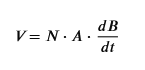
at  50Hz dB/dt when peak B is +/- 1Tesla is ~ 300 tesla per second. But as above here A is only 2/10000 of a square metre, so the volt per turn at saturation is about 600/10000 or 60mV (if you prefer about 15 turns per volt. TPV)

    Note we don't normally saturate cores, and for conventional (voltage )transformers at 50Hz, when  run backed down from saturation to get sensible core losses, another 'rule of 16' for those who like them, a transformer steel core minimum magnetic area of 16mm by 16 mm is about right for 16 turns per volt..

    In any case at say the high end of a real CT of that small core style is 15 TPV with 2000 turns the unloaded saturation OC voltage implies <~ 120V max.  

    This contrasts sharply with  far bigger dangers from  bus mounted CTs with far larger cores (square inch sort of cross sections to go round bigger conductors, so lower TPV, or higher VPT! but also more seriously with greater turns ratios, to bring primary side kA down to something sensible on the secondary).

    If operated unloaded these larger cores can generate many hundreds of volts, and in some cases, as well as having scope for killing an unskilled operator, can actually break down the insulation at the terminals and support some impressive arcing.  (while doing so, also dropping that fraction of a volt as one "turn" winding on the bus-bar.)
    Mike

    PS 

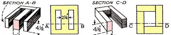
     Areas shaded pink are the limiting core areas in these designs. Ignore the ancient 'inch' notation. Unless you want to memorize  8 turns per volt per 1 inch square core area for 50Hz  transformer steels instead....

  • Needs a double plus good marking for that student Smiley

  • Also a lot of "consumer" CTs have either a burden resistor or voltage-clamping (e.g. back to back zeners) built-in.

        - Andy.

  • Agree, and to clarify we mean anti-series Avalanche or Zener diodes, not anti-parallel. You can get some nice ones you can plug into a cheap PC sound "card" with good LF response  with just the burden resistor added, that allow you to look at waveform qualityand harmonic analysis.

  • the insulation from the meter tails is not the problem,

    No, it's the insulation and protection of the conductors from the current transformer, and of the current transformer itself, because of the voltages created. We no longer have 'limitation of discharge of energy', and there are good reasons for that.

    These conductors are not SELV ... so they must be FELV or LV ... and you see where this goes from here in BS 7671 terms.

  • Also a lot of "consumer" CTs have either a burden resistor or voltage-clamping (e.g. back to back zeners) built-in.

    I'm not 100 % sure this is the case ... and if it is, what if those devices fail? 'Guaranteed SELV' CTs are very expensive!

Reply
  • Also a lot of "consumer" CTs have either a burden resistor or voltage-clamping (e.g. back to back zeners) built-in.

    I'm not 100 % sure this is the case ... and if it is, what if those devices fail? 'Guaranteed SELV' CTs are very expensive!

Children
  • One example: https://www.makerhero.com/img/files/download/SCT013-Datasheet.pdf

    Failure of the voltage clamping must be possible of course.It would have to be part of a chain of failures to become hazardous though - e.g. circuit broken circuit plus failed basic insulation, or being dismantled/disconnected without taking the basic precaution of unclipping it from the meter tails as well as the monitored circuit carrying a significant current at the moment concerned - combined with the chances of the voltage clamping itself failing. So maybe not drastically more dangerous than say ADS where the simple failure of a c.p.c. can entirely remove protection.

    The high voltage is associated with an infinite impedance of an open circuit though - to get a shock presumably a body resistance (in the region of 1kΩ?) would have to be in-circuit and therefore limit the voltage (and current) available to some extent?

       - Andy. 

  • Failure of the voltage clamping must be possible of course.It would have to be part of a chain of failures to become hazardous though - e.g. circuit broken circuit plus failed basic insulation,

    The device you linked to has an audio jack on it, so only one fault (failed resistor) is necessary.

    However, that is also based on the assumption that the burden resistor type is selected. The 1 V output is pretty non-standard for a monitoring interface in a building, because there could well be a problem with EMC if there's a long-lead connection in an installation.

    I've certainly seen a lot that are a basic current transformer, no built-in burden resistor, with simple insulation on the leads for connection - these only need a single fault (open-circuit conductor) to be a hazard.

  • Unfortunately, that ship is already passing through the harbour entrance and heading out into the world.  Consumer CTs intended to clip round meter tails with whatever protection their suppliers deem appropriate have been out there for over 20 years (at least since the first home energy monitors appeared in the 1990s) and the fitment rate is taking off rapidly with the proliferation of EVSE and PV.  Some of them make a nice buzzing sound if clipped round a tail without being connected - I'm not sure whether that is internal arcing or the operation of a protective device and haven't had the time to investigate.

    Ideally we would have rolled out a simple standard interface giving basic electrical data (voltage, current, power, etc.) as part of the smart meter roll-out, completely avoiding the need for clip on CTs (a great application for cheap plastic fibre optics, since only uni-directional communication over relatively short distances is required).

    (I also note that smart meters are probably the logical place for things such as a standardised approach to G100 style CLSs (especially in a domestic setting and if multiple manufacturers devices need to work together) and possibly even open PME neutral detection, but maybe I'm getting a little controversial now...).

  • Ideally we would have rolled out a simple standard interface giving basic electrical data (voltage, current, power, etc.) as part of the smart meter roll-out, completely avoiding the need for clip on CTs (a great application for cheap plastic fibre optics, since only uni-directional communication over relatively short distances is required).

    For energy management, it's important to be able to look at import and export current as well as voltage.

    There are alternative approaches, where an energy monitoring unit (that has CTs and VTs built in) connects in-line with the tails, and communicates via CANbus/Modus back to the energy management system (e.g. inverter).

    Consumer CTs intended to clip round meter tails with whatever protection their suppliers deem appropriate have been out there for over 20 years (at least since the first home energy monitors appeared in the 1990s) and the fitment rate is taking off rapidly with the proliferation of EVSE and PV. 

    Agreed ... it's those I'm talking about, not all are installed correctly (and as discussed above, perhaps some are not installed in accordance with BS 7671).

  • The device you linked to has an audio jack on it, so only one fault (failed resistor) is necessary.

    Fair point. Of course wire-ended versions are available too. Interestingly Victron seem to have switched from plugs to hard-wired in their recent models - they might have had similar thoughts.

       - Andy.

  • as part of the smart meter roll-out, completely avoiding the need for clip on CTs

    Except that sometimes what's meant to be measured doesn't necessarily pass completely and individually through the supplier's meter - e.g. total generation for PV or consumption for specific load (heat pump or EV). Mind you extending the smart meter system to PV generation meters might not have been a bad idea...

        - Andy.