There appears to be an error in 312.2.1.1 Single-source systems.
Note 4(b): "Regulation 8(4) of the Electricity Safety, Quality and Continuity Regulations (ESQCR) prohibits the use of a public distribution network neutral as a protective conductor in consumers' installations."
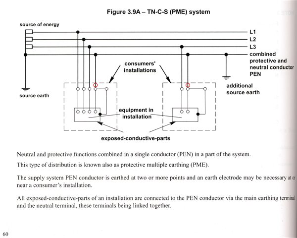
So why is a short length shown in Figure 3.9A, circled in red below? (I realise that the figure is not new.)
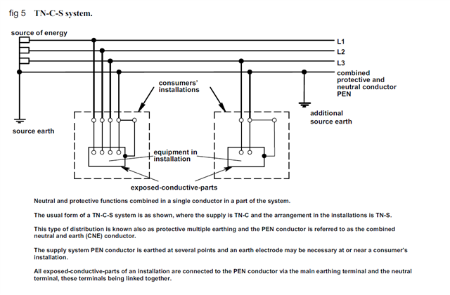
I appreciate that the aim may be to show the distinction between the TN-S and TN-C-S (PNB) systems where there is no link on the consumer's premises on the one hand, and TN-C-S (PME) where there is a link in each of them on the other hand.
The fact is that the service head, which contains the link, is part of the network, so the links in Figure 3.9A ought to be shown outside the dashed box. Alternatively, the boxes could be re-labelled as "consumers' premises".
As a point of interest, an electricity meter is normally to be situated on a customer's premises (Paragraph 1(3) of Schedule 7 to the Electricity Act 1989), so the adjacent service head will be situated on the same premises.
ESQCR defines “consumer’s installation” as "the electric lines situated upon the consumer’s side of the supply terminals together with any equipment permanently connected or intended to be permanently connected thereto on that side", and “supply terminals” as "the ends of the electric lines at which the supply is delivered to a consumer’s installation" (Reg 1(5)). “Supply neutral conductor” is "the neutral conductor of a low voltage network which is or is intended to be connected with earth, but does not include any part of the neutral conductor on the consumer’s side of the supply terminals".
Given that the network and consumer's installation are unambiguously demarcated at the supply terminals, it follows that Note 4(b) cannot be correct. Whether the supply terminals are the output of the service head or the output of the meter does not change the argument.
What R.8(4) of ESQCR states is "A consumer shall not combine the neutral and protective functions in a single conductor in his consumer’s installation." In other words, it prohibits a consumer from using any of his own neutral conductors as a protective conductor rather than a public one. I suggest that the distinction is more than trivial.