Earthing Arrangements for Enclosures

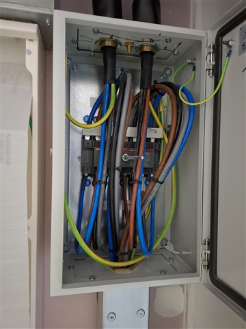
A & B supplies going through manual transfer switch to 2No DBs. 
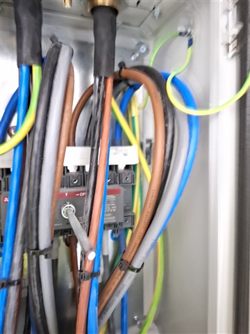
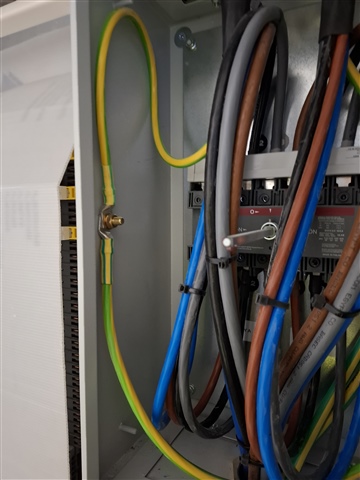
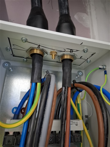
I'm concerned that this enclosure and CPCs are not bonded or installed correctly. I've also got concerns that the switch isn't wired correctly, according to the schematic. 
Bonding
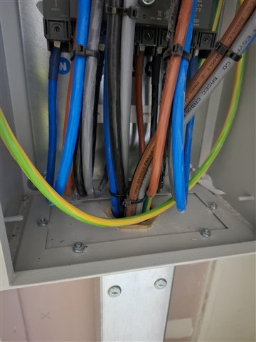
  • The SWAs have been glanded into the removable panels but there is no fly-lead connecting to the main enclosure. As far as I'm aware there is a rubber seal between the removable panel and the main enclosure to maintain the IP rating. I appreciate there are nuts and bolts holding this in place, but would this be sufficient as a connection? 
  • The CPCs from the supply have been bonded to the side panel of the housing, and the CPCs from the DBs have been bonded to rear panel of the housing but they have not been connected together. Although everything is connected through the housing it doesn't appear to be a robust connection. 
Switch
ABB 0T100F4C
Schematic arrangement below. 
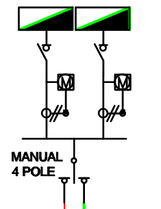
From the data sheets and diagrams available from ABB, I don't believe the switch operates how the schematic is drawn. Meaning that essentially supply A is connected to one side of outputs from the switch and supply b connected to the other side. The switch provides 3 modes of operation - All off, Side I on with Side II off, and Side II on with side I off. 
I'd like to hear thoughts and opinions on this please.
      
Parents
  • Well, the part no you give is for a 100A four pole centre off double throw switch, if that helps clarify at all. (docs.rs-online.com/.../0900766b811b91ea.pdf)
    As regards the earthing of the gland plates, the simplest thing is to do a continuity test between gland plate or better the armoured cable, and the box. If the glands and the bolts that hold the plates on have firmly crushed star washers and/or there is no paint under the nut and head contact surfaces, and the test is OK then that's likely to remain satisfactory. However, if there is any doubt about that (and a damp atmosphere may be enough to introduce doubt about how long a clean connection may last, especially if dissimilar metals are involved) then a suitably bosky link may well be in order. Any parts that may be opened up or moved for maintenance should also be considered at risk of not being put back tightly, and should also have a bond.
    Mike.

  • OK, now you have added some pics.
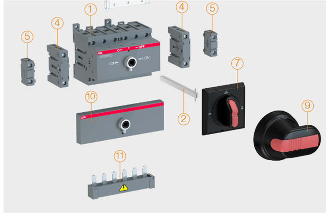
    Its not clear, but I think the paler grey part may be the bus-link. I dont have quite the right drawing here but for this similar model note that the optional extra 

    part 11 is a short length of 3 pole bus, that is used to make the common terminal common, as opposed to a set of six or eight totally independent single pole contacts. It can of course be fitted top or bottom or neither but in your case only makes sense on the non-supply side.  If not then there should be something simialr somewhere else.
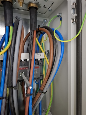
    Those terminations are impressively long and loopy it must be said ;-)  ' leave a bit of slack for any re-work' has been rather over done and it is hard to see how it is wired.

    Mike. 

  • Indeed - those large loops look to me like they could mean there's only one layer of basic insulation between live conductors and the door - which calls into question the little links between door and main enclosure - the pics are a bit fuzzy but they look like standard "blue" crimps - so would take 2.5mm2 max - which feels a bit slim for a 100A circuit (if that's what we have).

    It does look suspiciously like they're relying on the G/Y core as c.p.c. and haven't given a lot of consideration to earthing the armour - I suppose that might be OK if the armour is connected adequately at the "other" end(s).

       - Andy.

Reply
  • Indeed - those large loops look to me like they could mean there's only one layer of basic insulation between live conductors and the door - which calls into question the little links between door and main enclosure - the pics are a bit fuzzy but they look like standard "blue" crimps - so would take 2.5mm2 max - which feels a bit slim for a 100A circuit (if that's what we have).

    It does look suspiciously like they're relying on the G/Y core as c.p.c. and haven't given a lot of consideration to earthing the armour - I suppose that might be OK if the armour is connected adequately at the "other" end(s).

       - Andy.

Children
No Data