Hoping someone can help me with a question on the wiring requirements for a 12kw electric boiler.
For context, I’m attempting to have a botched installation rectified after the manufacturer said the warranty had been invalidated by an incorrect installation (both plumbing and wiring aspects). I’m not an electrician and I’ve had a couple of electricians look at it now and received different answers.
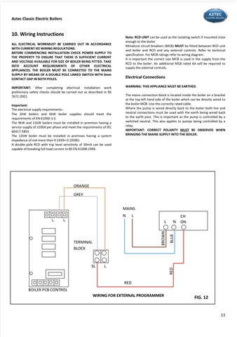
The boiler in question is a Trianco Aztec Classic 12kw (installation manual here: https://heatingpartswarehouse.co.uk/wp-content/uploads/2023/06/Aztec-Classic.pdf). The relevant page for the wiring instructions is 16.
My specific question is whether the boiler and the external wiring controls (we have a Reliance 8 zone wiring centre) should be on separate circuits? The wiring requirements state: “Miniature circuit breakers (MCB) MUST be fitted between RCD unit and boiler and RCD and any external controls….An additional MCB rated 6A will be required to supply the external controls.”
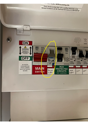
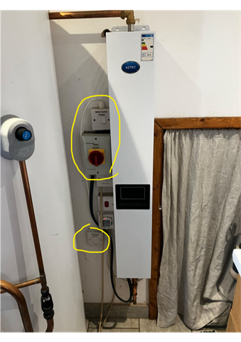
The current setup is the boiler and controls are on a 63A type B RCBO, with a switched fused spur on the same circuit for the controls. Whether this was ever correct/appropriate for the previous boiler I can’t say, but the installer has obviously just tried reuse what was already there on a like-for-like basis with the new boiler (different manufacturer/model).
One electrician has said the external controls should have been installed on a separate circuit with its own MCB, and the other that it can be on the same circuit and just replace the fused spur with a 6A MCB.
Happy to provide more information and grateful if there’s anyone with experience with electric boilers that may be able to help.