Automatic Transfer Switching - Dual Supplies - Neutral Earthing

I am inheriting an existing design to review (the installation has been completed for a number of years).

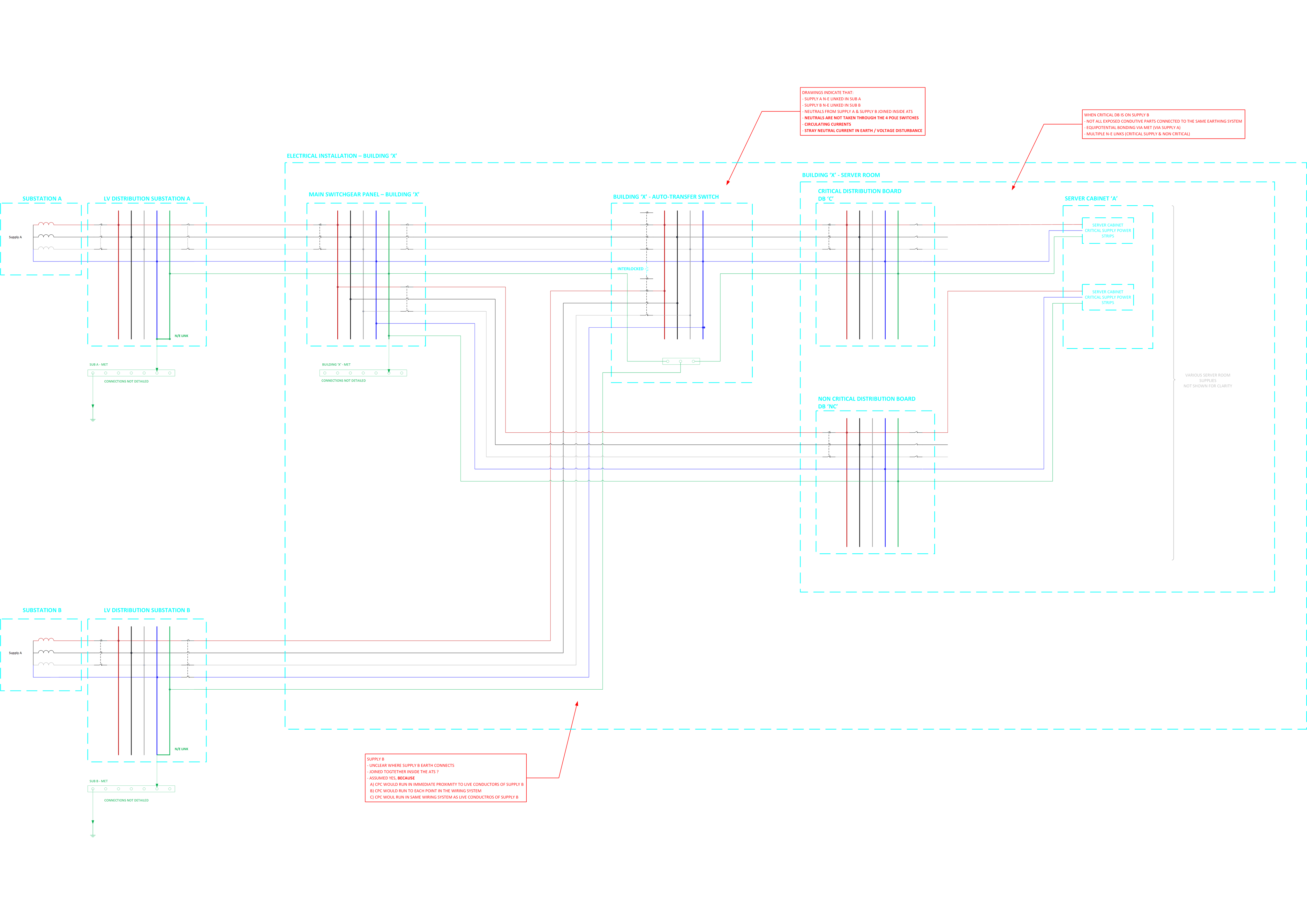
The installation is fed from a main supply "Supply A (from Sub A) and supply A N-E link is in the upstream LV substation.

The installation has a server room with a critical distribution board, the critical DB is fed from an automatic transfer switch

  • The ATS is fed by two supplies
  • One supply to the ATS is derived from Supply A
  • The other supply to the ATS is derived from another supply "Supply B (from Sub B)"
  • Supply B N-E link is in the upstream LV substation.
  • The neutrals of supply A and supply B are connected together in the ATS
  • The ATS changeover switch uses 3 pole breakers (neutrals are not switched)
  • Inside the server room there is a mix of 1) Equipment supplied by supply A non critical and 2) Equipment supplied by supply B critical
  • The ATS appears to have 4 pole changeover switches but only 3 of the poles are used (neutral not switched) 

Please see attached sketch for the five wire diagrams

To my mind there is a lot to be desired about this but I want to double check my thinking by running it past the community:

  1. Two N-E links present
  2. Neutrals linked inside the installation
  3. Not all exposed conductive parts connected to the same earthing system (supply A and supply B)?
  4. Circulating currents and voltage disturbance
  5. Stray neutral currents flowing to earth
  6. Issues with protection
  7. Etc.

What are your thoughts?

Thanks

Richard

/resized-image/__size/14034x14034/__key/communityserver-discussions-components-files/4/WIring-Regulations-_2D00_-Protective-Measures-ADS-and-Earthing-Conductors.png

Parents
  • Based on your description, I share your concerns. Unless there is a common upstream source with a single earthing arrangement, permanently linking the neutrals of two independent TN systems within the ATS is generally undesirable. A 3-pole ATS with an unswitched neutral effectively parallels the neutral conductors of Supply A and Supply B, even when only one source is supplying the load.

    Potential consequences include:

    • Circulating neutral currents between the two transformer substations due to differences in neutral-earth potential.
    • Unpredictable earth fault current paths, which can affect protective device operation.
    • Stray currents on CPCs and other bonded metalwork.
    • Difficulties with fault finding and isolation, as the “dead” source may still carry neutral current.

    If the supplies originate from separate transformers with independent N-E links, a 4-pole ATS with switched neutral would normally be the preferred arrangement to keep the systems separated during transfer. The fact that the ATS appears capable of four-pole switching but has only three poles utilised raises the question of whether this was a design decision or an installation oversight.

    I would also want to establish whether the two substations are part of the same LV network or genuinely independent sources, and whether the DNO or designer intended the neutrals to be interconnected. That information is fundamental before concluding non-compliance.

    • It would be interesting to hear whether others have encountered similar legacy installations, particularly in data centres or healthcare environments where resilience requirements often complicate conventional earthing arrangements.
Reply
  • Based on your description, I share your concerns. Unless there is a common upstream source with a single earthing arrangement, permanently linking the neutrals of two independent TN systems within the ATS is generally undesirable. A 3-pole ATS with an unswitched neutral effectively parallels the neutral conductors of Supply A and Supply B, even when only one source is supplying the load.

    Potential consequences include:

    • Circulating neutral currents between the two transformer substations due to differences in neutral-earth potential.
    • Unpredictable earth fault current paths, which can affect protective device operation.
    • Stray currents on CPCs and other bonded metalwork.
    • Difficulties with fault finding and isolation, as the “dead” source may still carry neutral current.

    If the supplies originate from separate transformers with independent N-E links, a 4-pole ATS with switched neutral would normally be the preferred arrangement to keep the systems separated during transfer. The fact that the ATS appears capable of four-pole switching but has only three poles utilised raises the question of whether this was a design decision or an installation oversight.

    I would also want to establish whether the two substations are part of the same LV network or genuinely independent sources, and whether the DNO or designer intended the neutrals to be interconnected. That information is fundamental before concluding non-compliance.

    • It would be interesting to hear whether others have encountered similar legacy installations, particularly in data centres or healthcare environments where resilience requirements often complicate conventional earthing arrangements.
Children
No Data