Automatic Transfer Switching - Dual Supplies - Neutral Earthing

I am inheriting an existing design to review (the installation has been completed for a number of years).

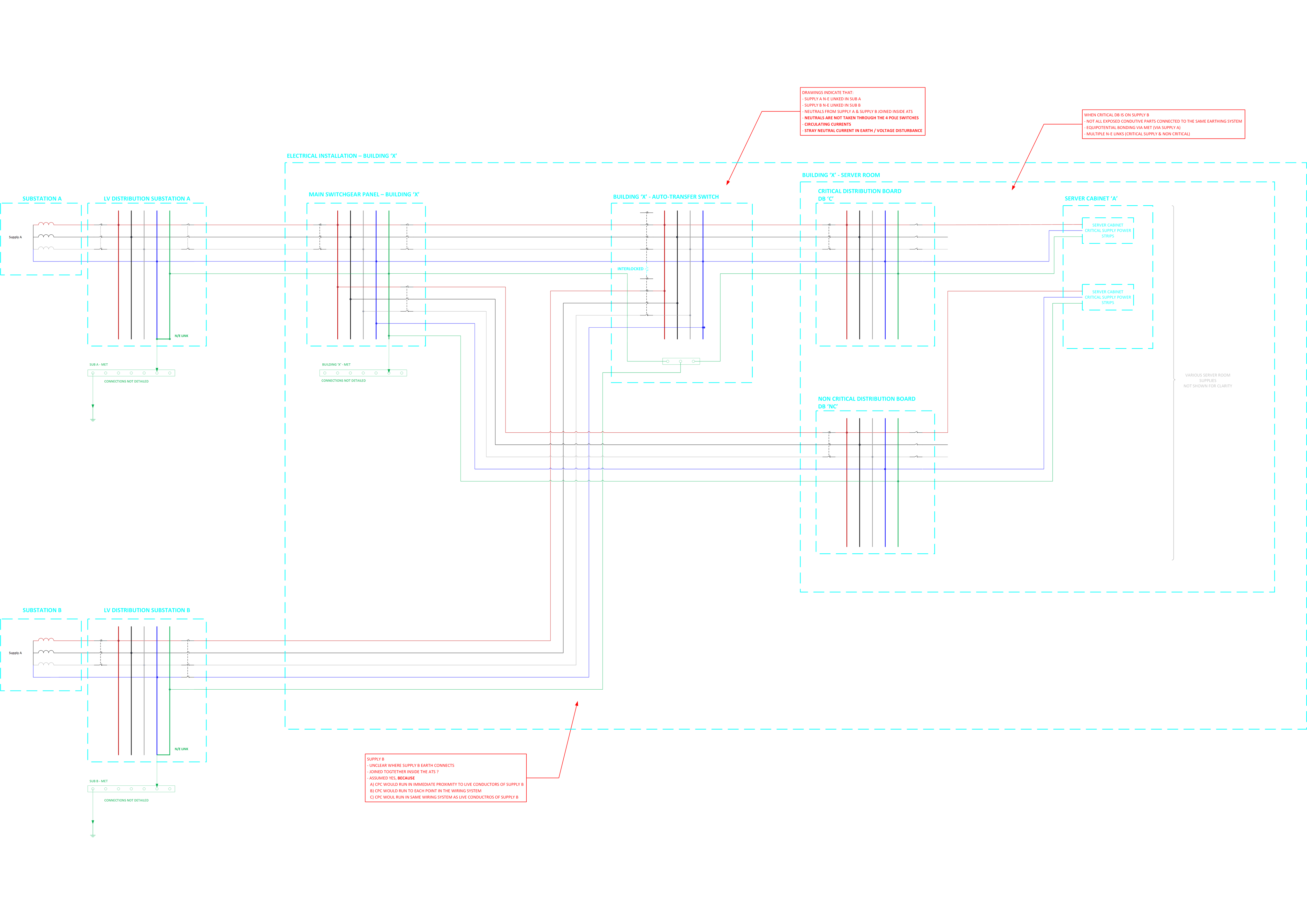
The installation is fed from a main supply "Supply A (from Sub A) and supply A N-E link is in the upstream LV substation.

The installation has a server room with a critical distribution board, the critical DB is fed from an automatic transfer switch

  • The ATS is fed by two supplies
  • One supply to the ATS is derived from Supply A
  • The other supply to the ATS is derived from another supply "Supply B (from Sub B)"
  • Supply B N-E link is in the upstream LV substation.
  • The neutrals of supply A and supply B are connected together in the ATS
  • The ATS changeover switch uses 3 pole breakers (neutrals are not switched)
  • Inside the server room there is a mix of 1) Equipment supplied by supply A non critical and 2) Equipment supplied by supply B critical
  • The ATS appears to have 4 pole changeover switches but only 3 of the poles are used (neutral not switched) 

Please see attached sketch for the five wire diagrams

To my mind there is a lot to be desired about this but I want to double check my thinking by running it past the community:

  1. Two N-E links present
  2. Neutrals linked inside the installation
  3. Not all exposed conductive parts connected to the same earthing system (supply A and supply B)?
  4. Circulating currents and voltage disturbance
  5. Stray neutral currents flowing to earth
  6. Issues with protection
  7. Etc.

What are your thoughts?

Thanks

Richard

/resized-image/__size/14034x14034/__key/communityserver-discussions-components-files/4/WIring-Regulations-_2D00_-Protective-Measures-ADS-and-Earthing-Conductors.png

  • Based on your description, I share your concerns. Unless there is a common upstream source with a single earthing arrangement, permanently linking the neutrals of two independent TN systems within the ATS is generally undesirable. A 3-pole ATS with an unswitched neutral effectively parallels the neutral conductors of Supply A and Supply B, even when only one source is supplying the load.

    Potential consequences include:

    • Circulating neutral currents between the two transformer substations due to differences in neutral-earth potential.
    • Unpredictable earth fault current paths, which can affect protective device operation.
    • Stray currents on CPCs and other bonded metalwork.
    • Difficulties with fault finding and isolation, as the “dead” source may still carry neutral current.

    If the supplies originate from separate transformers with independent N-E links, a 4-pole ATS with switched neutral would normally be the preferred arrangement to keep the systems separated during transfer. The fact that the ATS appears capable of four-pole switching but has only three poles utilised raises the question of whether this was a design decision or an installation oversight.

    I would also want to establish whether the two substations are part of the same LV network or genuinely independent sources, and whether the DNO or designer intended the neutrals to be interconnected. That information is fundamental before concluding non-compliance.

    • It would be interesting to hear whether others have encountered similar legacy installations, particularly in data centres or healthcare environments where resilience requirements often complicate conventional earthing arrangements.
  • I can sort of understand a reluctance to switch Ns on 3-phase systems - especially those with a number of single-phase loads - as any imperfection in timing that results in N open when two or more lines are connected, even momentarily, can lead to severe overvoltages (e.g. 400V being presented to 230V equipment) - which tends not to end well. Probably even more of a worry with switch-mode power supplies, as N currents are even less likely to cancel nicely.

    The belt and braces approach is to open the lines, verify they have all opened correctly, then open N, the close the N of the secondary supply, verify that that's happened OK and only then connect the lines of the secondary supply. Maybe your ATS does that, maybe it doesn't. Even if it does, that might result is a much longer transfer time ... so critical loads probably want a UPS downstream of the ATS as well. There might be an argument for an UPS anyway - relying on a 2nd feed alone for critical loads is a bit "old hat" these days - I'm fairly certain it's no longer a recognised approach for safety-critical systems. All the data centres I've been to in recent years have their own backup generators (and UPSs to cover the generator startup).

    Not all exposed conductive parts connected to the same earthing system (supply A and supply B)?

    The two supply PEs look to be solidly connected together - so we've sort of got one earthing system common to both supplies (perhaps not unlike the situation where bonded metallic water or gas mains cross between substation boundaries - which doesn't seem to cause problems in practice).  Conductors between the supplies and thee common point would have to be appropriately sized of course (something akin to main bonding perhaps).

    Etc.

    If I was feeling particularly argumentative, I might observe the N on one supply would carry some of the earth fault currents associated with the other .. which might be interpreted as combining neutral and earthing (protective) functions in a single conductor within a consumer's installation ... which is prohibited (by law) in the UK by the Electricity Safety, Quality & Continuity Regulations (https://www.legislation.gov.uk/uksi/2002/2665/pdfs/uksi_20022665_en.pdf) reg 8(4).

      - Andy.

  • working on a large private network, I come across this sort of configuration quite often. 

    My opinion are as follows - 

    1. Each substation transformer have their own N-E link which is absolutely fine and correct design. 

    2. Neutral of supplies from two substations should ideally not be interconnected downstream for the reasons you already stated - circulating current, RCD or CB/relay derived earth fault protection maloperation if any, potential standing voltage in PE  etc.

    3. The ATS should ideally be switching neutral. Although there is a risk of neutral breaking first or making last causing overvoltage across single phase load but that risk is negligible for correctly selected ATS from reputed manufacturer which generally have EMLB(Early make late break neutral) tested for thousands of operations. This sort of configuration is invariably use for supplies from different source - Mains and Generator for example where you must switch neutral. 

    4. The LV earthing maybe combined provided both subs are cold sites and the corresponding earthing is designed for similar fault level, disconnection times etc. If one is hot and other is cold it won’t be a good idea. I understand they are private transformers so should be okay given the above is ensured.

  • Some thoughts. 

    Firstly in countries without an ESCQR multiple NE bonds are not uncommon where there are secondary supplies or standby generation. The one nearest to the UK practice in all other aspects is probably Southern Ireland.

    The actual problems it causes in practice are minimal. The biggest issue is that earth fault relays and RCDs see the other NE link as a fault, and that the CPC and neutral share any fault current, and both need to be sized accordingly for the maximum current, or there is scope for overload.

    Note that on the distribution side pre any consuming equipment interlinked NE or even a shared PEN  would be common  think PME, its on the load side of the installation it is not permitted.

    One big earthing system is entirely correct as you cannot separate what is supplied from where, there is no problem with the other supply providing an additional electrode. Do confirm that any one is adequate in term of Ze and Zs, as the whole point is that one or other of the supplies may actually be off-line or totally disconnected for repair and the system kept alive by the other.

    parallel neutrals is the dodgy part, and switching with an offset contact so neutral breaks later than phases and makes before is the common solution.

     but as noted, the real risk is low.

    M.

  • Hi All,

    Thanks everyone for the replies - very informative. 

    Please see below for responses (collated from everyone's responses in one place)

    A 3-pole ATS with an unswitched neutral effectively parallels the neutral conductors of Supply A and Supply B, even when only one source is supplying the load.

    The ATS specification originally asked for a 4 pole automatic transfer switch with overlapping neutral i.e. Supply B neutral conductor make, supply A line conductors break, supply B line conductors make, supply A neutral conductor break.  This doesn't appear to have been carried into the design.

    If the supplies originate from separate transformers with independent N-E links, a 4-pole ATS with switched neutral would normally be the preferred arrangement to keep the systems separated during transfer.

    Agree - per "444.4.7 Transfer of supply"

    I would also want to establish whether the two substations are part of the same LV network or genuinely independent sources, and whether the DNO or designer intended the neutrals to be interconnected.

    They are from different LV substations on an large industrial site. Thinking more deeply it is likely that a global earthing system is in effect across site due to density of buildings, earth electrode nests, substations, etc

    especially those with a number of single-phase loads - as any imperfection in timing that results in N open when two or more lines are connected, even momentarily, can lead to severe overvoltages (e.g. 400V being presented to 230V equipment)

    This is an interesting point of clarification - If the 4 Pole ATS with "guaranteed" momentary overlapping of the neutral were installed (per the original specification) then this risk seems to be mitigated.

    Maybe your ATS does that, maybe it doesn't

    As above.

    so critical loads probably want a UPS downstream of the ATS as well

    The design does include for local UPS backup within the server room - the ATS is there to ensure that the UPS autonomy time is not exceeded and that delay from switching over from supply A to Supply B are prevented.  I believe the ATS is operating "in line" but could transfer to internal bypass so I am not accounting for any isolation from input to output side.

    no longer a recognised approach for safety-critical systems

    Agree - The ATS and second supply from supply B and UPS are intended for mission critical equipment (not safety critical)

    The ATS should ideally be switching neutral. Although there is a risk of neutral breaking first or making last causing overvoltage across single phase load but that risk is negligible for correctly selected ATS from reputed manufacturer which generally have EMLB(Early make late break neutral)

    Agree - please see above

    The LV earthing maybe combined provided both subs are cold sites and the corresponding earthing is designed for similar fault level, disconnection times etc

    Are you considering the earth potential rise on the MV side here i.e. ensuring the means of earthing of supply A does not overlap with an EPR zone (>470 V?) of the means of earthing of supply B?

    I understand they are private transformers

    Correct

    The actual problems it causes in practice are minimal. The biggest issue is that earth fault relays and RCDs see the other NE link as a fault, and that the CPC and neutral share any fault current, and both need to be sized accordingly for the maximum current, or there is scope for overload

    parallel neutrals is the dodgy part, and switching with an offset contact so neutral breaks later than phases and makes before is the common solution.

     but as noted, the real risk is low.

    Agree - as above the original intent / specification was 4 pole ATS with momentary overlapping neutral which seems to be optimal but for some reason not implemented.  I will investigate implementing an improvement on this topic.

    Thanks everyone for their insightful contributions!

    Richard


  • transfer switch with overlapping neutral i.e. Supply B neutral conductor make, supply A line conductors break, supply B line conductors make, supply A neutral conductor break. 

    Even that sounds less than ideal .. I can see upstream RCDs for one not being happy during the 'both N connected' period.

      - Andy.

  • EPR

    Yes, exactly. It’s 430V though for standard protection. 

  • Even that sounds less than ideal .. I can see upstream RCDs for one not being happy during the 'both N connected' period.

    This is a valid point. But I think when the ATS was installed this may have been the best option. For modern ATS, overlapping neutral is generally not required and switched neutral is preferable as the neutral is on the same contact bar so it doesn’t really have the risk of transient voltage even in unbalanced load conditions. This is generally guaranteed by the manufacturer. 

  • Two N-E links present

    That effectively turns a TN-S supply into a TN-C-S supply.

    The bringing together of the N and PE to form two parallel combined neutral and protective conductors (CNE conductors), can cause all sorts of issues - some have already been discussed.

    In the UK, Wiring Regulations and later BS 7671 have prohibited the practice of recombining N and PE once they have been separated for over 45 years. Specifically Regulation 543.4.3 from BS 7671:2008 onwards, previously 546-02-08 between 1991 and 2008 in the 16th Edition, and 546-8 in the 15th Edition introduced in 1981. Further, this practice being poor practice for EMC has been recognised in Regulation 444.4.6 since the introduction of BS 7671:2008.

    A similar prohibition is in place in IEC 60364-5-54, and has been like that for some time too, as well as IEC 60364-4-44 from 2007 onwards.