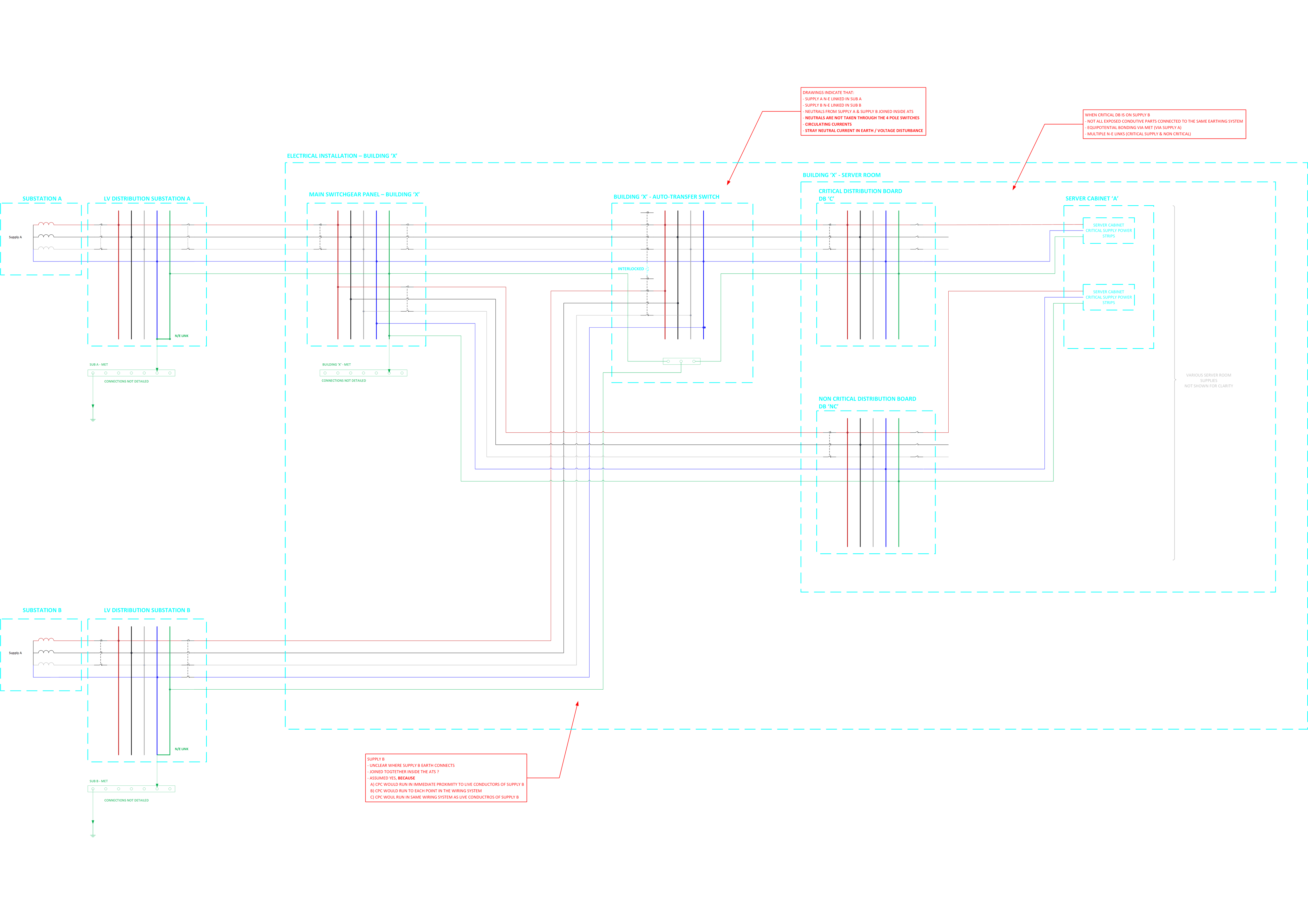
Automatic Transfer Switching - Dual Supplies - Neutral Earthing

I am inheriting an existing design to review (the installation has been completed for a number of years).

The installation is fed from a main supply "Supply A (from Sub A) and supply A N-E link is in the upstream LV substation.

The installation has a server room with a critical distribution board, the critical DB is fed from an automatic transfer switch

  • The ATS is fed by two supplies
  • One supply to the ATS is derived from Supply A
  • The other supply to the ATS is derived from another supply "Supply B (from Sub B)"
  • Supply B N-E link is in the upstream LV substation.
  • The neutrals of supply A and supply B are connected together in the ATS
  • The ATS changeover switch uses 3 pole breakers (neutrals are not switched)
  • Inside the server room there is a mix of 1) Equipment supplied by supply A non critical and 2) Equipment supplied by supply B critical
  • The ATS appears to have 4 pole changeover switches but only 3 of the poles are used (neutral not switched) 

Please see attached sketch for the five wire diagrams

To my mind there is a lot to be desired about this but I want to double check my thinking by running it past the community:

  1. Two N-E links present
  2. Neutrals linked inside the installation
  3. Not all exposed conductive parts connected to the same earthing system (supply A and supply B)?
  4. Circulating currents and voltage disturbance
  5. Stray neutral currents flowing to earth
  6. Issues with protection
  7. Etc.

What are your thoughts?

Thanks

Richard

/resized-image/__size/14034x14034/__key/communityserver-discussions-components-files/4/WIring-Regulations-_2D00_-Protective-Measures-ADS-and-Earthing-Conductors.png

Parents
  • working on a large private network, I come across this sort of configuration quite often. 

    My opinion are as follows - 

    1. Each substation transformer have their own N-E link which is absolutely fine and correct design. 

    2. Neutral of supplies from two substations should ideally not be interconnected downstream for the reasons you already stated - circulating current, RCD or CB/relay derived earth fault protection maloperation if any, potential standing voltage in PE  etc.

    3. The ATS should ideally be switching neutral. Although there is a risk of neutral breaking first or making last causing overvoltage across single phase load but that risk is negligible for correctly selected ATS from reputed manufacturer which generally have EMLB(Early make late break neutral) tested for thousands of operations. This sort of configuration is invariably use for supplies from different source - Mains and Generator for example where you must switch neutral. 

    4. The LV earthing maybe combined provided both subs are cold sites and the corresponding earthing is designed for similar fault level, disconnection times etc. If one is hot and other is cold it won’t be a good idea. I understand they are private transformers so should be okay given the above is ensured.

Reply
  • working on a large private network, I come across this sort of configuration quite often. 

    My opinion are as follows - 

    1. Each substation transformer have their own N-E link which is absolutely fine and correct design. 

    2. Neutral of supplies from two substations should ideally not be interconnected downstream for the reasons you already stated - circulating current, RCD or CB/relay derived earth fault protection maloperation if any, potential standing voltage in PE  etc.

    3. The ATS should ideally be switching neutral. Although there is a risk of neutral breaking first or making last causing overvoltage across single phase load but that risk is negligible for correctly selected ATS from reputed manufacturer which generally have EMLB(Early make late break neutral) tested for thousands of operations. This sort of configuration is invariably use for supplies from different source - Mains and Generator for example where you must switch neutral. 

    4. The LV earthing maybe combined provided both subs are cold sites and the corresponding earthing is designed for similar fault level, disconnection times etc. If one is hot and other is cold it won’t be a good idea. I understand they are private transformers so should be okay given the above is ensured.

Children
  • Some thoughts. 

    Firstly in countries without an ESCQR multiple NE bonds are not uncommon where there are secondary supplies or standby generation. The one nearest to the UK practice in all other aspects is probably Southern Ireland.

    The actual problems it causes in practice are minimal. The biggest issue is that earth fault relays and RCDs see the other NE link as a fault, and that the CPC and neutral share any fault current, and both need to be sized accordingly for the maximum current, or there is scope for overload.

    Note that on the distribution side pre any consuming equipment interlinked NE or even a shared PEN  would be common  think PME, its on the load side of the installation it is not permitted.

    One big earthing system is entirely correct as you cannot separate what is supplied from where, there is no problem with the other supply providing an additional electrode. Do confirm that any one is adequate in term of Ze and Zs, as the whole point is that one or other of the supplies may actually be off-line or totally disconnected for repair and the system kept alive by the other.

    parallel neutrals is the dodgy part, and switching with an offset contact so neutral breaks later than phases and makes before is the common solution.

     but as noted, the real risk is low.

    M.