Automatic Transfer Switching - Dual Supplies - Neutral Earthing

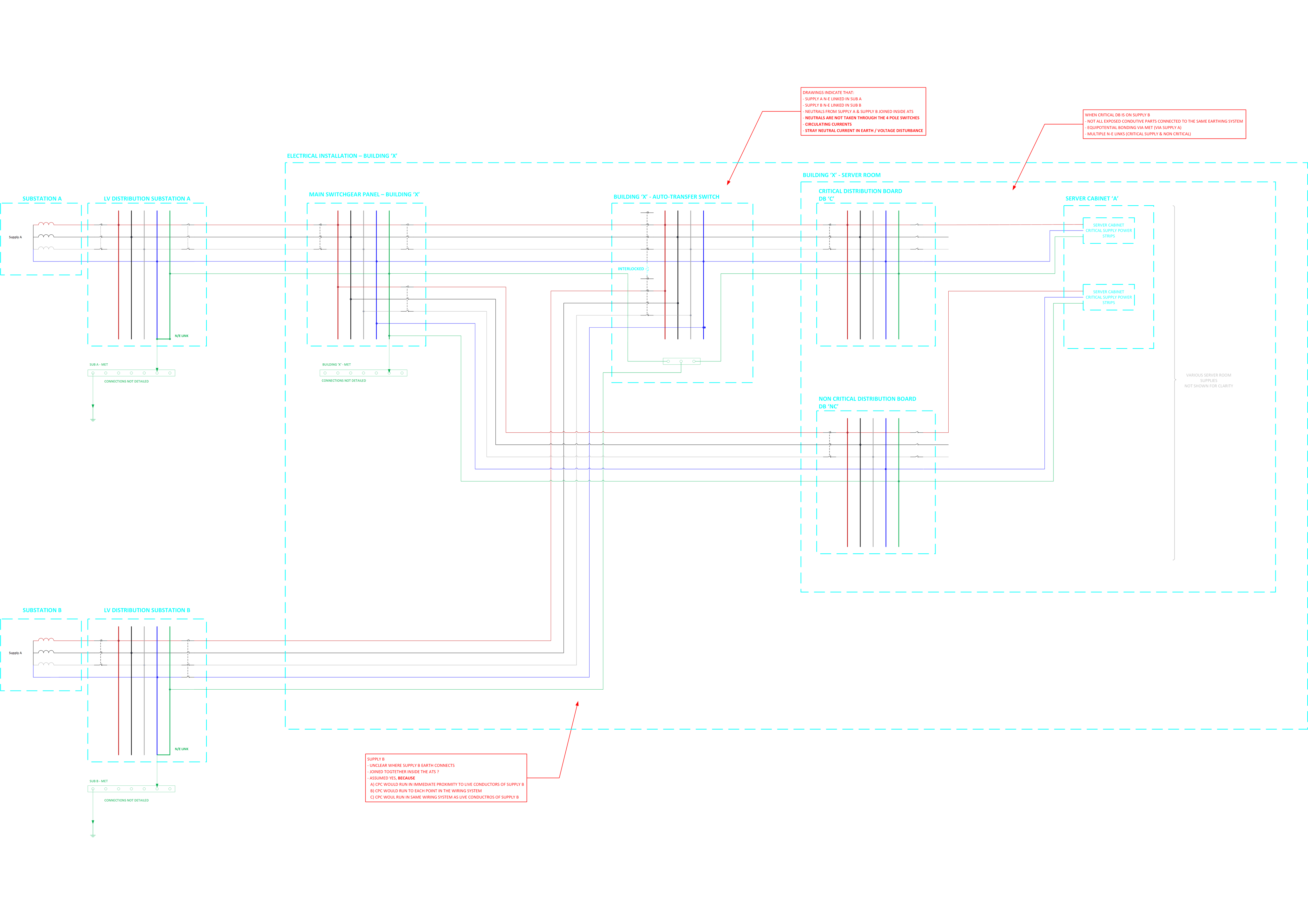
I am inheriting an existing design to review (the installation has been completed for a number of years).

The installation is fed from a main supply "Supply A (from Sub A) and supply A N-E link is in the upstream LV substation.

The installation has a server room with a critical distribution board, the critical DB is fed from an automatic transfer switch

  • The ATS is fed by two supplies
  • One supply to the ATS is derived from Supply A
  • The other supply to the ATS is derived from another supply "Supply B (from Sub B)"
  • Supply B N-E link is in the upstream LV substation.
  • The neutrals of supply A and supply B are connected together in the ATS
  • The ATS changeover switch uses 3 pole breakers (neutrals are not switched)
  • Inside the server room there is a mix of 1) Equipment supplied by supply A non critical and 2) Equipment supplied by supply B critical
  • The ATS appears to have 4 pole changeover switches but only 3 of the poles are used (neutral not switched) 

Please see attached sketch for the five wire diagrams

To my mind there is a lot to be desired about this but I want to double check my thinking by running it past the community:

  1. Two N-E links present
  2. Neutrals linked inside the installation
  3. Not all exposed conductive parts connected to the same earthing system (supply A and supply B)?
  4. Circulating currents and voltage disturbance
  5. Stray neutral currents flowing to earth
  6. Issues with protection
  7. Etc.

What are your thoughts?

Thanks

Richard

/resized-image/__size/14034x14034/__key/communityserver-discussions-components-files/4/WIring-Regulations-_2D00_-Protective-Measures-ADS-and-Earthing-Conductors.png

Parents
  • Two N-E links present

    That effectively turns a TN-S supply into a TN-C-S supply.

    The bringing together of the N and PE to form two parallel combined neutral and protective conductors (CNE conductors), can cause all sorts of issues - some have already been discussed.

    In the UK, Wiring Regulations and later BS 7671 have prohibited the practice of recombining N and PE once they have been separated for over 45 years. Specifically Regulation 543.4.3 from BS 7671:2008 onwards, previously 546-02-08 between 1991 and 2008 in the 16th Edition, and 546-8 in the 15th Edition introduced in 1981. Further, this practice being poor practice for EMC has been recognised in Regulation 444.4.6 since the introduction of BS 7671:2008.

    A similar prohibition is in place in IEC 60364-5-54, and has been like that for some time too, as well as IEC 60364-4-44 from 2007 onwards.

Reply
  • Two N-E links present

    That effectively turns a TN-S supply into a TN-C-S supply.

    The bringing together of the N and PE to form two parallel combined neutral and protective conductors (CNE conductors), can cause all sorts of issues - some have already been discussed.

    In the UK, Wiring Regulations and later BS 7671 have prohibited the practice of recombining N and PE once they have been separated for over 45 years. Specifically Regulation 543.4.3 from BS 7671:2008 onwards, previously 546-02-08 between 1991 and 2008 in the 16th Edition, and 546-8 in the 15th Edition introduced in 1981. Further, this practice being poor practice for EMC has been recognised in Regulation 444.4.6 since the introduction of BS 7671:2008.

    A similar prohibition is in place in IEC 60364-5-54, and has been like that for some time too, as well as IEC 60364-4-44 from 2007 onwards.

Children
No Data