Who is responsible for non compliantbev install

EICR on 3 year old house thats a rental property. C2 because ev charger is sharing an rcd with other circuits in a split load board.Complied with how many organisations interpreted the regulations at the time of design.

No.high integrity ways available, only practical solution is replace the board or additional board for the ev charge point. Could consider rebuilding the internals of the existing cu, but still time consuming and fairly expensive.

Just generally interested in how the as long as it complied at the time approach works.

Who is responsible for the costs?

Parents
  • The safety of the EVSE is not compromised, the risks arise on all the other circuits that share the upfront 30 mA RCD.

    Just to compound the issues, in a couple weeks time after the 27th August 2026 the tenants may buy some plug in PV with a disconnection time on loss of supply of two seconds, which takes the maximum disconnection time of the RCD protected circuits out to 2300 milliseconds, 2000 mS for the PV plus 300 mS, plug in two PV units protected by the upfront RCD and it may never trip.

    And therein lies the problem, if the EVSE is sharing an upfront 30 mA RCD with socket circuits, no one can really anticipate how the tenant will use them and what they will plug in that will affect the performance of the circuit protection, particulary the upfront 30 mA RCD. If you are preparing the EICR whilst the house is empty prior to letting, how can you determine if thre installation will be safe when the tenants move in and start using it?

    So, if the EVSE is pushing the upfront RCD to the limits of its performance, it cannot cope with having other circuits to protect as well.

  • Just to compound the issues, in a couple weeks time after the 27th August 2026 the tenants may buy some plug in PV with a disconnection time on loss of supply of two seconds, which takes the maximum disconnection time of the RCD protected circuits out to 2300 milliseconds, 2000 mS for the PV plus 300 mS

    Not if you have a DP RCD - the plug-in PV may hold up the L-N voltage downstream of the RCD but as long as the RCD has physically tripped and so opened the N connection, what's downstream should be pretty much floating w.r.t. Earth - so shock currents very limited (i.e. just what can sneak through filters on Class I equipment and the like - as as that should be below 9mA if it's on a 30mA RCD, the shock risk seems pretty low in practice).

    (I thought the proposed UK version of the standard had a much shorter disconnection time on power fail too - I'll have to check that).

    So, if the EVSE is pushing the upfront RCD to the limits of its performance, it cannot cope with having other circuits to protect as well.

    Which limit? If it's cumulative leakage (sorry, protective conductor) current, then at worst it's going to nuisance trip - so no additional shock risk there. If it's blinding then an A type in the CU together with a RCD-DD in the EVSE seems to tick all the boxes (provided there's only one EVSE). Selectivity etc. certainly point to it being a pretty shoddy approach - certainly not what I'd want at home, but that not usually enough to make it a BS 7671 C2. If the CU RCD was an AC type, or an A type and the EVSE didn't include an RDC-DD,  then you could conclude that the RCD could be compromised - so loss of additional protection - so C3 for indoor circuits, perhaps a C2 for any circuits feeding mobile equipment outdoors or bathroom circuits if there wasn't supplementary bonding. I'm not saying it can't be a C2, I'm just suggesting it's quite so simple as 'sharing an rcd with other circuits in a split load board' is always potentially dangerous.

       - Andy.

  • (I thought the proposed UK version of the standard had a much shorter disconnection time on power fail too - I'll have to check that).

    To save time.. 

    The interim UK standard says two things. The first about ceasing to generate AC.

     In deviation of ES1 (for laypersons) of Table 5 of BS EN IEC 62368-1:2024+A11:2024,
    the inverter shall automatically disconnect from the mains supply within 100
    ms.
    The voltage at accessible plug pins shall decrease to below 34 V within 100 ms following

    disconnection from mains supply. NOTE: This requirement is taken from DIN VDE V 0126‑95.

    but if the plug is pulled out then a longer applies time in respect of stored charge that may leave a DC voltage between isolated but accessible parts if there is no load. 

    For plug pins without contact protection, there is a risk that the internal capacitor may maintain
    hazardous voltage on the plug pins for a short period following AC disconnection. For normal
    operation, the voltages at accessible plug pins shall comply with the ES1 limits (for laypersons)
    in Table 5 of BS EN IEC 62368-1:2024. Following disconnection from mains supply,
    capacitors larger than 100nF shall discharge to a voltage not exceeding 34 V within 1 s.

     In the case of the supply side RCD opening, then its probably the upper 100msec  time that applies, as there will still be LN loads connected to that will draw current and run down the caps a lot faster than the 'unplugged bare pins' case.

    More generally I agree - sharing an RCD with sockets that may have almost anything plugged in, even the humble induction motor, will extend the time fro, when the  RCD contact opens to the voltages dropping to a safe level, however this is not a new thing, and is why generally we test RCDs with things unplugged or suffer occasional silly readings.

    However it is important to be clear, that additional over-run is not special to plug-in solar, which if anything is more tightly regulated than many situtions.

    Mike.

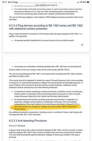
  • I quoted the 2 seconds from memory, that requirement is actually here.

  • yes, that's the 'electromechanical solution ' by which I assume they mean they want a contactor or a mechanical switch - but the inverter has stopped outputting any AC voltage long  (well,  1.9 seconds ) before that has to operate. M.

  • It seems there is a blending of requirements from three sources in the UK specification, a bit of mix and matching going on.

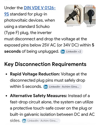
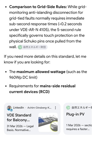
    An internet search result throws up this response.

  • Yep, it was one of my comments that the interim spec was a bit of a cut and shut job from various standards, and it would have been better to show the working and or the relevant excepts in full.

    For a writing team that is not confident  I can see the attraction of copying like this - 'limits  as per BS EN XXXX' gives the feeling of a bit of 'top cover' whereas deriving the requirement from scratch requires someone to act as design authority and be happy to sign off on their reasoning about risk of death by heart fibrillation or starting fires. Such cross -referencing instead of original work is increasingly common.

    However, I also think the feeling of security is often probably false, as there is a real risk that  the situation the donor standard was intended for is not quite the same.

    As a killer example the Grenfell Tower cladding passed an inappropriate glow wire fire spread test  because of the heat sink action of the metal foils, but still burnt like something between candle-wax and solid rocket fuel in a real fire. The two situations should never have been assumed to be equivalent, but by a desk study only it could be made to look like it had been tested for spread of fire and passed.  The fact that the unsuitable tests were referred to deliberately, and the actual fire performance was known but not mentioned,  made the substitution criminal rather than incompetent, but to a non-technical buyer who does not really know what exactly is written in each standard at all a certificate meeting a selection of impressive standards XYZ it gave the illusion of being suitable. (we see this all the time with EMC standards as well but the results are more irritating than deadly )

    Coming back to the plug-in inverter, if I was designing it, I can see no reason for a late-acting mechanical switch at all - the simple requirement that it must stop generating within 5 cycles and any DC must fall away smartly is all that is really needed.

    There is no need to have a separate much easier test case for the 'unplugged' situation from the main 'supply removed or tripped' as the same mechanism will act on both. But I'm neither writing the standard or designing anything to meet it ;-) 

    Mike.

  • Mike, issue I’m having as you have probably guessed is I’m acquiring information in many ways, talking to people face to face, online and live events, books, websites and even the car radio, then trying to collate it all in my head.

    It appears that with plug in PV the intention is to use the anti-islanding technology to provide both basic and fault protection, but this will only operate after the circuit protective devices have operated, so the disconnection times should be quicker, but there remains the doubt that the anti-islanding technology can operate correctly with multiple plug in PV systems downstream of a shared RCD and if the possibility that the upfront RCD may be blinded by the total DC leakage current.

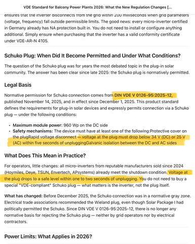
    A screenshot from LinkedIn.

  • t appears that with plug in PV the intention is to use the anti-islanding technology to provide both basic and fault protection, but this will only operate after the circuit protective devices have operated,

    And consider that we (unlike Germany) have extensively used single-pole RCBOs, meaning that, if there's a fault on the circuit the plug-in PV is connected in, or a person comes into contact with a live part on that circuit or an appliance connected to it, even if the RCBO operates properly, the actual disconnection time from the user's perspective is increased by the anti-islanding time ... the anti-islanding time alone is longer than the 40 ms the RCD has to operate within for 'lethal' residual currents.

Reply
  • t appears that with plug in PV the intention is to use the anti-islanding technology to provide both basic and fault protection, but this will only operate after the circuit protective devices have operated,

    And consider that we (unlike Germany) have extensively used single-pole RCBOs, meaning that, if there's a fault on the circuit the plug-in PV is connected in, or a person comes into contact with a live part on that circuit or an appliance connected to it, even if the RCBO operates properly, the actual disconnection time from the user's perspective is increased by the anti-islanding time ... the anti-islanding time alone is longer than the 40 ms the RCD has to operate within for 'lethal' residual currents.

Children
  • You have my sympathy, I  agree the whole thing  is more than a  bit muddled; so muddled actually that no inverter maker has yet to dare to put their head above the parapet and said their unit is definitely fine with the UK plug in spec. with less than 3 weeks to plug-in day, (presumably holding off just in case it was not compliant after all !)

    It is a very general thing that a victim on a socket circuit, with stuff plugged in, is more likely to be exposed to lethal time current combination due to an over-voltage persisting longer than the ADS of the circuit with nothing plugged in would have assured; its another one of those hidden assumptions... These effects are also true of generation during motor spin-down and some SMPS  that have capacitors on the mains, that if they are the only thing plugged in at the time,   leave the L& N some painful volts apart at DC for well over 400msec. Usually there is some near resistive load plugged into another socket as well to get rid of that, but not always.

    The responsibility of the circuit installer does not really include worrying too much about the changes in behaviour once things are plugged in, as you have almost no control over it.  (though the change from AC to A RCD types suggest that this is only partly believed.)

    In the same way product standards assume the supply is not the finest, and that it is not sensible to rely on the CPC for things outdoors (except cars) or for many hand held tools, and there may be L-N reversal, as well as various EMC stimuli, and over and under-voltage and surge conditions that must be tolerated.

    Then to muddy the water further thanks to online ordering and direct shipping there is the huge range of stuff that gets plugged in anyway that is nothing like compliant with the product standards at all, bought and used by people who don't really realise that they have assumed the responsibilities of the importer. 

    Mike.

    Edit

    OK, the ENA register has been updated, 2 makers have put their kit in the ring, and at least for now, both are non compliant. Sigh!

    https://connect-direct.energynetworks.org/device-databases/search-gen?category_id=1&device_type_id=14 

  • OK, the ENA register has been updated, 2 makers have put their kit in the ring, and at least for now, both are non compliant. Sigh!

    The regulations do not change until 27th August, so today being the 11th, currently all Plug-in solar inverters are still non-compliant for use on DNO networks, so does that status reflect the state of the regulations not yet taking effect to permit Plug-in solar, or the assessment of the inverters? 

    I guess we can see if the status changes on 27 or 28th August.