Have your say on the Electrician’s Guide to Domestic Electric Vehicle Charging Equipment Installation

The Draft for Public Consultation (DPC) is available for the IET’s Electrician’s Guide to Domestic Electric Vehicle Charging Equipment Installation. This is your opportunity to review the draft and provide feedback to help ensure the publication meets the needs of electricians, designers, installers and other professionals working with electric vehicle (EV) charging equipment. 

As EVs become increasingly common across the UK, the demand for safe, and compliant charging installations continues to grow. This guide has been developed to provide practical guidance on the selection, design, installation and certification of domestic EV charging equipment, helping practitioners navigate the technical and regulatory requirements associated with this rapidly evolving sector. 

What the guide covers 

The draft publication provides a comprehensive overview of domestic EV charging installations, including: 

  • The various EV charging modes and types of charging equipment 
  • Relevant regulations, standards and key sources of information 
  • Assessment considerations before system design and installation 
  • Methods of electrical protection and earthing 
  • Domestic and small commercial installation design, including control devices, circuit design and cabling 
  • Certification and documentation requirements 

Bringing together essential technical guidance and industry best practice, the guide is intended to support both experienced electricians and those new to EV charging installations. 

Why your input matters 

The DPC provides an opportunity for industry professionals to help shape a practical and authoritative resource for the electrical sector. Whether you are involved in EV charger installation, inspection and testing, electrical design, training or compliance, your feedback can help ensure the guidance remains relevant, accurate and aligned with current industry practice. 

Your comments will help strengthen the final publication, supporting safer installations and promoting consistency across the growing EV charging market. 

Visit the website to find out more and submit your comments by 21 August 2026: https://spkl.io/600073To0

  • Probably a consumer/marketing thing.

    Possibly ... the product standard for charging equipment permits the manufacturer to quote rated power or rated current.

  • I believe that while we commonly say how many kW a charger is, the EVSE tells the car how many amps it's allowed to draw.

    If I log into my EVSE through its app, I can set the maximum current the car is allowed to draw. I have mine set to 22A (for reasons*), which means that the car draws about 5 kW maximum.

    *A bit of a design flaw on the Renault Zoe. The connector where the charge port wiring loom meets the filter unit has an under-sized neutral. Because nobody would ever charge a car at 32A single phase, would they? Then they started exporting them to the UK, where home chargers, and many destination chargers, are single phase.

  • I was surprised it did not include some reference circuit design tables that considered all of the possible factors  for a typical EVSE install (volt-drop effects on Open-PEN detection, solar-gain when clipped direct in sunlight etc etc). to give a simple table or set of tables of reference designs, so that for the electrician wanting a suitable, prudent design with a reasonable safety margin they can simply use a proposed reference design, and avoid any risk of errors during various steps of calculation. The equivalent of what you get in the on-site guide but adjusted for EVSE applications.

    The other omission, and I may have missed it while skim reading through, but I didn't see anything about wiring accessories or terminal blocks and guidance on current rating of those - how much safety margin should be introduced for the continuous load implications, if the design load current is 32A it seems rather risky to use terminals/connectors etc rated for only 32A, is 40A advisible or even 50A? How much de-rating should be applied for the continuous load?

  • but I am not sure about the assessment of Ipf for 3-phase, page 110/111 and appendix F. Seems to use line to line calculation rather than the simultaneous fault all three phases. 

    Agreed - I spotted that and have included it in my comments.

    I think their whole approach for estimating worst-case fault currents for energy let-through purposes is wrong anyway - for MCBs the worst case is typically at the start of the circuit, not at the far end.

    If the whole thing is limited to MCBs, the whole rigmarole of trying to calculate the worst case fault current and plug it into S=SQRT(I²t)/k seem like trying to fit wheels on a tomato (to mis-quote Backadder's Dr Johnson)  Far simpler to just do what BS 7671 says and compare the I²t figure provided for the MCB with k²S² calculated for the cable - we could even tabulate common generic MCB let-through figures and pre-calculate S from those for the few values of k likely to be encountered - the design checks are then reduced to looking up figures in a couple of tables.

      - Andy.

  • I did the City and Guilds Domestic and Commercial EVSE course and gained the qualification five years ago, the syllabus has since been changed.

    When I took the exam the cable calculation was extremely basic.

    The tutor walked around the room with a pack of cards in each hand, one for a domestic installation and another for commercial installation, everyone got to pick a card from the pack, apart from me, I was given the last two remaining cards after everyone else had chosen theirs.

    Both of mine simply said that the EVSE required a 16-amp circuit and the cable was to be T&E clipped direct, the only difference was the length of the circuit.

    So all I had to do was select a cable size from the regs book and confirm the voltage drop was okay, so for both I wrote down that I could use 1.5 mm T&E and what the voltage drop would be, confirming it was okay, referencing BS7671 Table 4D5, but I will use 6.0 mm.

    That was it, I didn’t have to determine what the design current was, I was told it was 16-amps.

    I have been told that now a full cable calculation is required and electricians have been failing the exam as result of this to the extent that on one occasion only one out of twenty electricians passed the exam. I asked several electricians if they had been advised to revise the cable calculation before going on the course and they said no, if they had known what was expected they would have revised and prepared themselves in advance.

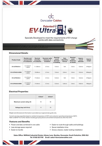
    Doncaster Cables make their specialised EVSE cables in both 4.0 and 6.0 mm, and state “These cables are designed to be installed in air, clipped to surface, on cable tray/ladder work and embedded in concrete. The cables can be laid direct in the ground providing that suitable mechanical protection is in place.” Then go on to say the 4.0 mm is rated at a maximum of 45-amps, which could easily lead to complacency as there appears to be more than enough capacity, but if only a short amount of the cable runs through an insulated building the could be some considerable derating to be factored in to the design.

    www.doncastercables.com/.../EV_Ultra_Datasheet...pdf

  • So is the takehome message that you need to wire your EVCP in 6 mm2 cable?
    Not necessarily - it's still permitted to handle overload and faults separately - if the EVSE provides overload protection, the cable still need only be sized for 32A provided it's c.s.a. has enough withstand for the B40 fault clearance (54000 A²s for a 6kA device - or just over 2mm² Cu for k=115). (double check the c.p.c. though if T&E)

    So Andy says, may be, may be not.

    I suspect that the rated diversity factor is more important. After all, if it is as low as 0.5 and the breaker cannot be kept separate from other continuous high loads, a 63A one will be required.

  • I noted at least one grammar error, can’t recall where.

    2.2.2 4th paragraph, and 6.3.3 1st paragraph: that should be roll and not role.

  • The only comment I'll make is why so many pages? 174, surely that can be brought down significantly. Such a tome is hardly going to be read by many, whereas if it was concise, and at around 50 pages, more people would attempt to read it, and understand its core principles.
    From my experience, there will be few coalface contractors who will be waiting with bated breath for this unwieldy tome and even less who will be able to follow the design process set out therein.

    Well, I spent a good chunk of this morning reading through it, skimming in parts.

    I agree that such a lengthy book will be off-putting. It seems a lot for what is, after all, a very simple radial circuit which is serving just one socket-outlet.

    The take-home points for me were:

    • be careful about diversity in the CU
    • apply all the cable rating factors (although there may be none)
    • be careful about cascading RCDs (Figure A53.2 of BS 7671 is reproduced)
    • take account of the manufacturer's instructions, which may require you to read a number of them before choosing the EVCP.
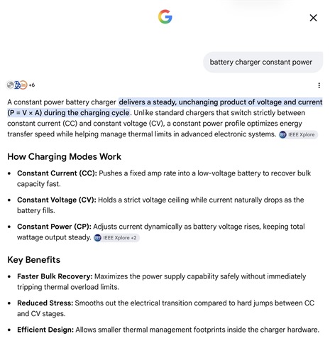
  • I asked Google about “battery charger constant power”

  • Yes, the EVSE signals the maximum available current to the EV using the Control Pilot pin in the charging cable, the EVSE can then operate upto that limit, as required.

    That current limit signal, depending on the EVSE hardware and the installation, can be used very simply as a fixed limit, or it can be varied dynamically to provide smart charging functionality, to manage the load at the house, or on a circuit, or to control charging to track the output from solar generation to self-consume solar, or for smart charging with time of use tariff.