Cable selection for Max fault current

For Fault at load end: The cable has to withstand the thermal stress for the through fault.

For Fault at the circuit breaker terminal side or (at the beginning of the cable): if the fault happened, it is understood that cable is already damaged, so there is no need to check the thermal stress for this case.

Refer to BS7671 clause 434.5.2, " A fault occurring at any point in a circuit shall be interrupted within a time such that the fault current does not cause the permitted limiting temperature of any conductor or cable to be exceeded"

Is the intent of this clause is that the fault do not develop in to "Fire" hazard though the cable is damaged, therefore cable thermal stress to be checked for faults at the beginning of the cable as well.

Is my understanding correct?

Parents
  • You are correct. When carrying out a thermal withstand calculation on a cable it should be done at the supply end and the far end of the cable to verify the cable is suitable for use.

    That said the far end of the cable is likely to be more onerous as the disconnection time will be longer due to the impedance of the cable being higher than the supply end.

    The far end may be a long, slow, blow heating up the cable for longer.

    When teaching this on the 2396 design course I found this the hardest concept for the students to understand. To illustrate this I had a slide showing potatoes being added to a carrier bag until it split with the potatoes representing energy and the bag as the thermal withstand of the cable. The thermal withstand being a re-arrangement of the adiabatic equation. 

    JP

  • With respect to the following:

    hen carrying out a thermal withstand calculation on a cable it should be done at the supply end and the far end of the cable to verify the cable is suitable for use.

    and 

    Yes, the thermal withstand shall be checked for both the If max. at the beginning of the cable and the If min. at the end of the cable.

    This is going to sound really pedantic, but actually, it's the entire length of the cable.

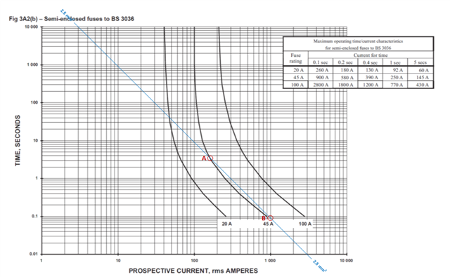
    For fuses, and in the thermal range of circuit-breakers, this is done for a selected cpc size by plotting the line corresponding  t=k2×S2/I2 over the time-current characteristic in Appendix 3, and checking that, for the range of prospective fault currents expected in the circuit, the line plotted is above and to the right of the fuse time-for-current line. In the example below, the two points where the fuse time-current line crosses the adiabatic line (2.5 sq mm) show that, provided the prospective fault current along the length of the cable is between around 130 A and around 1000 A, the adiabatic criterion is satisfied for a 45 A BS 3036 fuse and a 2.5 sq mm copper CPC:

    Hence, provided the prospective fault current exceeds 130 A at the far end of the cable, and is less than 1000 A at the consumer unit, everything is OK for that combination.

    Therefore, as   and  have said, in practice for fuses and in the thermal region of circuit-breakers, checking the adiabatic criterion is satisfied at the end closest to the distribution board, and the end of the circuit furthest away from the circuit board does the trick.

    For current-limiting devices, such as circuit-breakers operating in the magnetic region of their operating characteristic (less than 0.1 s), the calculation is slightly different, in that you still need to find the prospective fault currents at both ends of the cable, but this needs to be compared with the value of I2t either:

    (a) stated by the manufacturer in their data; or

    (b) stated by the product standard (which is usually higher)

    It is usually the case that the highest value of I2t corresponds to the highest value of prospective fault current found in a circuit protected by the magnetic portion of a circuit-breaker, which is usually at the consumer unit or distribution board end of the circuit.

    All of the above are explained (with examples) in Section 8 of the IET Electrical Installation Design Guide.

    See also this discussion thread: engx.theiet.org/.../table-41-3-max-zs-for-mcb-and-disconnection-times which has an interesting discussion on loop impedances and the difference between manufacturer's data for circuit-breakers, and the information provided in the tables in Chapter 41 for circuit-breakers to BS EN 60898 and RCBOs to BS EN 61009.

Reply
  • With respect to the following:

    hen carrying out a thermal withstand calculation on a cable it should be done at the supply end and the far end of the cable to verify the cable is suitable for use.

    and 

    Yes, the thermal withstand shall be checked for both the If max. at the beginning of the cable and the If min. at the end of the cable.

    This is going to sound really pedantic, but actually, it's the entire length of the cable.

    For fuses, and in the thermal range of circuit-breakers, this is done for a selected cpc size by plotting the line corresponding  t=k2×S2/I2 over the time-current characteristic in Appendix 3, and checking that, for the range of prospective fault currents expected in the circuit, the line plotted is above and to the right of the fuse time-for-current line. In the example below, the two points where the fuse time-current line crosses the adiabatic line (2.5 sq mm) show that, provided the prospective fault current along the length of the cable is between around 130 A and around 1000 A, the adiabatic criterion is satisfied for a 45 A BS 3036 fuse and a 2.5 sq mm copper CPC:

    Hence, provided the prospective fault current exceeds 130 A at the far end of the cable, and is less than 1000 A at the consumer unit, everything is OK for that combination.

    Therefore, as   and  have said, in practice for fuses and in the thermal region of circuit-breakers, checking the adiabatic criterion is satisfied at the end closest to the distribution board, and the end of the circuit furthest away from the circuit board does the trick.

    For current-limiting devices, such as circuit-breakers operating in the magnetic region of their operating characteristic (less than 0.1 s), the calculation is slightly different, in that you still need to find the prospective fault currents at both ends of the cable, but this needs to be compared with the value of I2t either:

    (a) stated by the manufacturer in their data; or

    (b) stated by the product standard (which is usually higher)

    It is usually the case that the highest value of I2t corresponds to the highest value of prospective fault current found in a circuit protected by the magnetic portion of a circuit-breaker, which is usually at the consumer unit or distribution board end of the circuit.

    All of the above are explained (with examples) in Section 8 of the IET Electrical Installation Design Guide.

    See also this discussion thread: engx.theiet.org/.../table-41-3-max-zs-for-mcb-and-disconnection-times which has an interesting discussion on loop impedances and the difference between manufacturer's data for circuit-breakers, and the information provided in the tables in Chapter 41 for circuit-breakers to BS EN 60898 and RCBOs to BS EN 61009.

Children