XLPE Twin & Earth - Appendix 4 Table - Method of install

Hi there,

I have a general technical query regarding installation methods and Appendix 4 tables for Twin & Earth cables.

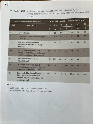
Table 4D5 is applicable to PVC/thermoplastic Twin & Earth. In this instance, with the cable installed in accordance with Reference Method 103 – within a stud wall with thermal insulation, with the insulation not touching the inner wall surface – a 2.5 mm² cable has a tabulated current-carrying capacity of approximately 13.5 A.

This can also be verified within ElectricalOM, where selecting Flat Twin 70°C PVC with CPC gives 13.5 A for 2.5 mm² under the relevant installation conditions.

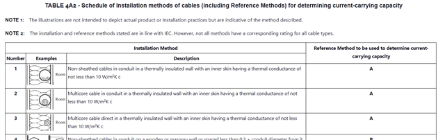
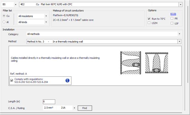
However, when selecting an XLPE Flat Twin & Earth cable (90°C thermosetting), ElectricalOM identifies the cable against Table 4E2. The software also provides an option to “Run to 70°C”. When this is selected, and Reference Method A No. 3 is selected, it gives a current-carrying capacity of 21 A for 2.5 mm².

My question is therefore whether this is an appropriate application of Reference Method A No. 3 for XLPE Twin & Earth installed within a thermally insulated stud wall.

In particular, where the installation is not relying on the 90°C operating temperature of the XLPE cable, is it permissible to use the 4E2 installation/reference-method arrangement but limit the conductor operating temperature to 70°C, resulting in the 21 A rating?

Or, when XLPE Twin & Earth is installed in this type of thermally insulated construction, should the 70°C PVC/thermoplastic values from Table 4D5 be used instead, despite the cable itself being a 90°C thermosetting/XLPE cable?

The particular installation I am considering is 2.5 mm² 6242B XLPE Twin & Earth, installed within a 90 mm stud wall with approximately 50–70 mm of thermal insulation surrounding the cable. The circuit has a design current of 11.26 A and is protected by a 20 A protective device.

I would appreciate clarification on which Appendix 4 table and reference method should correctly be applied in this situation, and whether the 21 A value obtained from ElectricalOM is an appropriate basis for the cable selection.

  • Reference Method A is in a conduit in a thermally insulating wall. It is NOT equivalent to Method 103# ... they are two different columns in Table 4D5.

    So, for 2.5 sq mm in Table 4D5, Reference Method A I get 20 A ... this seems to be very similar to the 21 A Electrical OM is giving you.

    So, I don't think you're comparing like-for-like.

    Are you installing the cable in a conduit in the wall, or not? If not, then you can't use Reference Method A you selected in Electrical OM ...

  • Hi thanks for your reply.

    yes i am currently not showing it in conduit, and i have used Reference A No. 3 - multicore cable as indicated, and not Ref. 103, as this is for PVC t&E.

    and within Elec OM this shows me this cable type is from 4E2 table, and when i put it as "In a thermally insulating wall" Method A No. 3 - it is giving me 21A for a 2.5mm cable:

    My issue is that people are taking the 4D5 derating table Reference 103 and showing this as only 13.5Amps.

    any further thoughts on this?

  • Note also the caveats - in all the higher current thermal approximations the cable is not supposed to be totally surrounded by insulation, but is expected to be able to cool by contact with and/or close proximity to one or other of the partition surfaces.
    10W/m2.K is equivalent to only 1cm of material of Thermal Conductivity 0.1 (W/m·K) (say like a sheet of plywood or plasterboard). Considering that Glass fibre or Celotex are at least  twice if not three times as insulating as this, you only need a 3-5mm layer of insulation on the supposedly cold side of the cable to use up all of that cold-side thermal resistance allowance -  for cooling out into partition wall, so now the wall surface itself needs to be aluminium or copper  to only just remain within specs.  Smile
    (it's just ohms law again but for heat - at least in solids or situations like foams and fur where the air cannot convect, the energy conducted is more or less linear with temperature gradient.)

    However the step down in rating from 20 odd amps to 13, is a huge drop in heat output, (I2R remember) so the cooling is being assumed to be literally 2.5 times worse.

    The reason is that there is also a huge difference between insulated on one side only, and insulated all round. Anecdotally we know this -compare rushing about wearing your coat like a cape that is open at the front, to wearing the same coat but buttoned up tight. 

    Mike


  • My issue is that people are taking the 4D5 derating table Reference 103 and showing this as only 13.5Amps.

    That's because it's a different situation - 103 is for a cable totally surrounded by thermal insulation - Method 3 (ref Method A) is for a cable in contact with the plasterboard one side and so is only partly covered with thermal insulation.

    If you cable is totally surrounded by insulation the 103 is correct - and if you're using 4D2 you'd probably need method C plus a correction factor for the insulation (likely 0.5) - e.g. 27 * 0.5 = 13.5 (see reg 523.9).

    If your cable is only partly surrounded by insulation and can loose heat through the plasterboard, then Method A would be correct, which would correspond to method 102 (rather than 103) in table 4D5.

    (as a bit of background, some years ago there wasn't a table 4D5 - we just used 4D2 for T&E just like for other sheathed cables. As thermal insulation became more common though, people were having trouble justifying using 2.5mm² T&E on ring circuits even though it seemed fine in practice. A bit of research confirmed that the shape of T&E (thinner sheath & larger surface area) meant it did have a somewhat higher current carrying capacity for the same c.s.a. compare with the round section cables 4D2 was designed for - and that small improvement often made the difference between a cable being satisfactory or just too small to meet the regs. Hence table 4D5 was called into creation.)

      - Andy.

  • A word to the wise, I would tell you to have a look in your IET Onsite Guide book, but if you bought it from Amazon it may have mistakes in it, like this one with a brown cover!