Testing of drossel filter

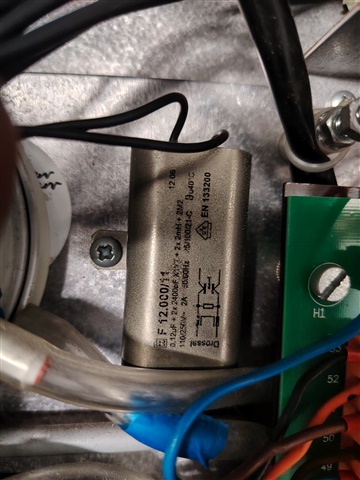
As above really can any one give an idea on the testing of this filter to confirm if faulty, never come across this type of filter, 

There was a gel type substance on the damaged one which caused some skin irritation but I want to prove it is faulty electrically , 

Parents
  • Possibly depends on what kind of fault you have in mind. Simple resistance and capacitance tests might do? (many up-market multimeters have a capacitance range built-in which might be convenient than having to do it from first principles).

    Gel substances sounds a bit like an electrolytic capacitor having a bad day - although I would have thought that plastic film type capacitors would have been more likely in a filter. I'm sure someone like Mike will be along soon to correct me.

       - Andy.

  • Drossel in ein Elecktrischer kontext in an electrical context, translates to 'choke' as in inductor or filter, its not a particular make or design of filter.
    This in the photos is just a standard EMI filter with a common mode ring choke and some shunt capacitance. An insulation test line to line will show if a cap is shorted, and a continuity test on each  line through will show the coil is unbroken. To do anything more advanced requires either a network analyser or a signal generator and some means of detection like a scope and one measures the attenuation as a function of frequency.

    Mains filters don't use electrolytic devices on AC, something like Mylar film, or occasionally ceramic cap designs, is more common. 

    The giblets may be potted in something like mastic or hot melt glue, that may have escaped, but the better ones are epoxy filled - does it look overheated perhaps, or has something been globbed over the top of  it, perhaps as anti vibration?

    Mike.

  • Perfect so just to summarise and so it's clear , I need to insulation test across each (shorter) end and continuity test across each line end to end (longer ) or have I understood that wrong ? 

  • Basically to summarise why we are suspecting this may be short , is that we had to replace the main PCB which then had the magic smoke appear and everything on the secondary side of the board was then shorted down to earth, we are suspecting this may have caused it however not 100% certain the replacement PCB was new. So just process of elimination now before we fit another and hopefully doesn't happen again 

  • yes - actually if you are not too worried about EMC you can probably test the downstream load without it, and you can certainly test it with something else as load.


    The circuit on your box should be interpreted as below, with the end with the word 'drossel' at the left, and it looks like the left hand CX may be omitted - if so it stops interference from  going in but not so much from coming out....

    Your pair of exit wires at the other end are P' and N' on this diagram. They may cross over in the box, it does not alter the operation and the meter will tell you. The earth "PE" and PE' are the mounting lugs.

    So from P to P' should be low resistance, verifying L (top winding)
    From N to N' the same, verifying L lower winding. Between P,N and PE high resistance - possible Rx between P and N, expect hundreds of k ohms or more. Or while its out on the bench you could put mains in on P N & E and connect any load you don't care about (workshop lamps or small heater perhaps) to P'N'E' and see that all works as it should.

    At 50Hz and DC the coil windings are small and can be treated as a short length of wire, because really they are, but  they do take time to respond to very fast changing currents and this will 'choke' the faster transient currents . Similarly at mains frequencies and below the capacitors are just an insulator between conductors - hence the symbol, but on a microsecond timescale that insulator can store and release charge, briefly holding the voltage up or down from sudden dips and peaks. Any surge or dip lasting more than a microsecond or two and the filter that size is not going to be able to do a lot.

    If that makes no sense, come back to me and I will try again.

    Mike.

  • Thank you, I will post readings when I get into work later today and see what we find, thanks for all your help so far 

  • There is a 2.2M resistor between the lines. So an insulation test may read lower than usual.

Reply Children
  • Ah yes sorry, the value is actually in the photo, so yes, expect a couple of megohms +/- 20% on the phase to neutral resistance reading. 20% as no cost-effective manufacturer would use anything tighter toleranced if it cost them more, and these seem to be "value engineered" units if they are omitting the left hand capacitor cluster.
    Filters work best in the direction L first, C  later, hence my comment above about suppression of interference in and out not being the same! Actually the really good ones have two sets of coils and 3 banks of caps, so which ever way something nasty is coming at you it always gets nobbled .)

    Anyway, prod it with the meter on ohms test first, and see what it tells you.

    Mike

  • So my findings so far

    Short end p-n 0Mohm on each end 

    p-p 0ohms 

    N- 0ohms 

    N-Pe 0.1Mohm

    P-pe 0.1mohm

    What do you think to these readings I think this is a broken filter 

  • Apologies p or n to pe is 100Mohm

  • Short end p-n 0Mohm on each end -

    If I understand you right, that means live is shorted to neutral internally and you have an educational paper weight...

    Do not try to use it. 

  • Yeh so just to clarify testing on the short ends (not across the the filter) I get that 0Mohm reading on insulation resistance , this would make sense why the PCB burnt out too with a dead short across a L/N

  • this would make sense why the PCB burnt out too with a dead short across a L/N

    Is the PCB upstream or downstream of the filter?

       - Andy.

  • Hi the PCB is upstream of the filter (before the filter) filter is then connected to a pactrol unit from the pcb