RCD used for ADS on a TN system: what verifies L-N circuit impedance?

I have been looking at the implications of using an RCD to provide ADS on a TN system under Regulation 411.4.204, rather than relying on the overcurrent characteristic of the MCB/RCBO.

Historically, where the overcurrent device provides ADS, Table 41.3 gives a relatively low maximum Zs. As well as demonstrating the required earth-fault disconnection time, this also provides a useful practical check on the integrity of the installed circuit.

Where an RCD is instead relied upon for ADS, Table 41.5 can permit a dramatically higher Zs. Previous EngX discussions confirm that this is a legitimate design approach on TN systems, although several contributors have also commented that measured Zs should still be reasonable for the circuit concerned. [engx.theiet.org], [engx.theiet.org]

My question concerns verification of the line-neutral fault path.

At design stage, software such as ProDesign performs separate line and earth fault adiabatic checks. It therefore determines minimum phase fault current and verifies that the overcurrent protective device will clear an L-N fault before the conductor's thermal withstand is exceeded. Trimble describes the software as performing both line and earth fault adiabatic checks. [engx.theiet.org], [trimble.com]

However, at initial verification the principal impedance value being recorded is Zs.

Consider a TN circuit where the design calculation assumes a low L-N loop impedance, but an installation defect introduces significant resistance into the line or neutral conductor.

If the RCD is relied upon for ADS, the measured L-E Zs could remain well within the Table 41.5 limit, because very little residual current is required to operate the RCD. Yet the actual L-N fault current could now be considerably lower than that assumed in the designer's Chapter 43 calculation.

Historically, where Table 41.3 governed, there was an indirect safeguard: if the L-CPC loop, often containing a CPC smaller than the neutral, had sufficiently low impedance to operate the MCB within the required time, there was considerable confidence in the L-N fault path as well.

When Table 41.5 is used for ADS on a TN system, what verification replaces that safeguard?

More specifically:

How does initial verification demonstrate that the as-installed L-N circuit impedance remains sufficiently close to the designer's calculated value for the minimum short-circuit current and Chapter 43 thermal withstand calculation to remain valid?

I appreciate that continuity measurements provide useful information and that an unexpectedly high Zs should be investigated rather than simply accepted because it is below the RCD-derived limit. But I am struggling to identify the explicit acceptance benchmark against which the verifier assesses this where the declared maximum Zs has been derived from the RCD rather than the overcurrent device.

Am I missing another requirement in BS 7671 or Guidance Note 3 that closes this loop?

Parents
  • The lack of a L-N loop impedance test is a long outstanding one

    Why? It is there in Chapter 64, but with another symbol and name - Ipf and prospective fault current! It's even in the same Section in Chapter 64 (643.7.3), see Regulation 643.7.3.201?

    TO convert between an 'impedance' and a 'prospective fault current', all you need to do is rearrange the formula:

    Zpf=V/Ipf, or Ipf=U/Zpf

    where
    U is the nominal voltage of the loop you are measuring (L-L, L-N)
    Ipf is the prospective fault current
    Zpf is the loop impedance corresponding to the prospective fault current.

    That's all the measuring instruments do to give you the loop impedance reading ... some loop test instruments, however, show both the prospective fault current they have measured, as well as the impedance value they have calculated.

    Another thing to remember about Section 643.7.3, for both EFLI and prospective fault current, is that neither is absolutely required to be measured ... either can be determined by another method (e.g. calculation or enquiry) instead.

  • I think we may still be talking about two different issues.

    I fully accept the requirements concerning maximum prospective fault current, breaking capacity and the suitability of the protective device. That is not the issue I am trying to explore.

    My question is specifically about the minimum prospective L-N short-circuit current at the remote end of the circuit, because that is the value on which the designer's fault disconnection time and Chapter 43 conductor thermal-withstand calculation depend.

    Where an RCD is deliberately relied upon for ADS on a TN system under Regulation 411.4.204, what part of initial verification confirms that the as-installed L-N loop impedance at the remote end remains sufficiently close to the designer's calculated value for the minimum L-N fault current and Chapter 43 calculation to remain valid?

    Historically, where ADS depended upon the MCB and Table 41.3, the maximum Zs requirement provided a useful indirect safeguard. If the L-CPC loop, often the higher impedance loop because the CPC may be smaller than the neutral, had sufficiently low impedance to operate the MCB within the required time, there was considerable confidence that the L-N fault path would also provide sufficient fault current.

    Once an RCD and Table 41.5 are used for ADS, that relationship largely disappears. A relatively high L-E loop impedance can still satisfy the ADS requirement because only sufficient residual current to operate the RCD is required.

    But the RCD does nothing for an L-N fault. The validity of the Chapter 43 calculation therefore still depends upon the actual L-N impedance being low enough to produce the minimum fault current assumed in the design.

    This leads to what I think is the key issue:

    There does not appear to be an equivalent BS 7671 table giving a maximum permissible ZL-N in the way that Tables 41.3 and 41.5 give maximum Zs values for ADS.

    The maximum permissible L-N impedance is therefore design-specific. It depends upon the protective-device characteristic, conductor size, k value and the resulting permissible fault-clearing time.

    Consequently, unless the designer provides the installer/verifier with either:

    • the calculated minimum L-N fault current, or
    • the corresponding maximum permissible ZL-N at the end of the circuit,

    what numerical acceptance criterion does the verifier actually have?

    The verifier can demonstrate continuity and polarity, and may establish that the circuit appears reasonable. But "reasonable" is not the same thing as demonstrating that the as-installed circuit satisfies the assumptions within the designer's Chapter 43 calculation.

    For example, if the designer calculated an end-of-circuit L-N loop impedance of 0.6 Ω but the completed installation actually had 1.5 Ω due to additional conductor resistance or a resistive connection, the conductor could still have continuity and correct polarity. The L-E Zs could also comfortably satisfy the much higher Table 41.5 value because the RCD provides ADS.

    Yet the actual L-N minimum fault current would now be much less than the designer calculated, potentially moving the MCB into a very different part of its time/current characteristic. The original Chapter 43 thermal-withstand calculation could therefore no longer be valid.

    That is the verification gap I am asking about.

    So I am not asking how initial verification establishes maximum PFC or whether the protective device has sufficient breaking capacity.

    I am asking:

    How does initial verification demonstrate adequate minimum L-N fault current at the remote end of an RCD-protected TN circuit?

    And, specifically:

    If BS 7671/GN3 does not provide a tabulated maximum ZL-N, doesn't the designer need to state the design-specific maximum ZL-N or minimum L-N fault current on the design information so that the installer has something against which the completed circuit can actually be verified?

    Otherwise, I struggle to see how the verifier can demonstrate that the as-installed Chapter 43 condition matches the design calculation, rather than simply demonstrating continuity, polarity and compliance with an RCD-derived maximum Zs that may be almost entirely unrelated to the required L-N fault current.

    That is the distinction I am trying to establish.

  • I think we may still be talking about two different issues.

    I fully accept the requirements concerning maximum prospective fault current, breaking capacity and the suitability of the protective device. That is not the issue I am trying to explore.

    My question is specifically about the minimum prospective L-N short-circuit current at the remote end of the circuit, because that is the value on which the designer's fault disconnection time and Chapter 43 conductor thermal-withstand calculation depend.

    If you look at my previous posts, you will see that the point is that I clearly said 'the maximum prospective fault current at all points in the circuit concerned.'

    This covers both the highest and lowest maximum prospective fault current.

    At this point, I'll ignore circuit-breakers ... this will become clear later. 

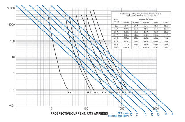
    So, you do NOT make the calculation simply at the highest (or lowest) prospective fault current point, precisely because there's a curve in the current-time ratings of a fuse vs the straight line (in the log-log graphs we use) for k2S2 plotted against I2. All of this is covered in Chapter 8 of the IET Electrical Installation Design Guide. For example, see Figure 8.2 of EIDG for BS 88-3 'gG' fuses:

    When we come to circuit-breakers, the disconnection time is less the 0.1 s, and BS 7671 tells us we need to use the I2t value specified by the manufactuer (or the device product standard) relating to the prospective fault current concerned.

    In general (although there are exceptions with circuit-breakers in particular), with fuses, often the worst-case conditions for Section 434 for fuses is given (assuming linear circuits) at a prospective fault current of CminIpf(min)(nominal), but with circuit-breakers operating in less than 0.1 s, the worst-case conditions are given at a prospective fault current of CmaxIpf(max)(nominal)

    Historically, where ADS depended upon the MCB and Table 41.3, the maximum Zs requirement provided a useful indirect safeguard.

    Agreed ... for ADS ... this does NOT relate to protection against overcurrent, though.

    If the L-CPC loop, often the higher impedance loop because the CPC may be smaller than the neutral, had sufficiently low impedance to operate the MCB within the required time, there was considerable confidence that the L-N fault path would also provide sufficient fault current.

    I'm not quite sure where that is going for an L-L or L-N fault, except to say that this is covered in a completely different Chapter in BS 7671.

    I am asking:

    How does initial verification demonstrate adequate minimum L-N fault current at the remote end of an RCD-protected TN circuit?

    And, specifically:

    If BS 7671/GN3 does not provide a tabulated maximum ZL-N, doesn't the designer need to state the design-specific maximum ZL-N or minimum L-N fault current on the design information so that the installer has something against which the completed circuit can actually be verified?

    Chapter 41 does NOT. An RCD is not an overcurrent protective device, and under the existing Harmonized version if IEC 60364-4-43, that aligns with BS 7671, an RCD does not appear to be able to provide protection against fault current.

    Otherwise, I struggle to see how the verifier can demonstrate that the as-installed Chapter 43 condition matches the design calculation, rather than simply demonstrating continuity, polarity and compliance with an RCD-derived maximum Zs that may be almost entirely unrelated to the required L-N fault current.

    What value of let-through energy are you using for the RCD, to conform to Regulation 434.5.2 when the disconnection time is less than o.1 seconds? What assumptions are you making (say in a TT system) for the changes in prospective fault current under different conditions?

    See Section 6.4 (starting page 107) of IET Guidance Note 6 Protection against overcurrent.

    Otherwise, I struggle to see how the verifier can demonstrate that the as-installed Chapter 43 condition matches the design calculation, rather than simply demonstrating continuity, polarity and compliance with an RCD-derived maximum Zs that may be almost entirely unrelated to the required L-N fault current.

    That is the distinction I am trying to establish.

    Again, you appear to be under the impression that BS 7671 requires something to be measured after the installation is completed ... as above, this is neither the case with ADS nor protection against fault current.

  • I understand the calculation you are describing, including the need to consider the range of prospective fault currents, Cmin⁡C_{\min}Cmin​, Cmax⁡C_{\max}Cmax​, protective-device characteristics and, where applicable, the manufacturer's I2tI^2tI2t data.

    I completely understand the design aspects. However, I still don't think that addresses the point I am trying to establish.

    I am not questioning how the designer carries out the Chapter 43 calculation. My question is what happens after that calculation, when the circuit has actually been installed and has to be verified. And RCD max Zs may introduce a different approach to verification. 

    The designer has necessarily made an assumption about the impedance of the L-N fault path at various points along the circuit. That impedance determines the prospective L-N fault current:

    If=UZL−NI_f=\frac{U}{Z_{L-N}}If​=ZL−N​U​

    That prospective fault current then determines the operating behaviour of the OCPD and hence whether the conductor is adequately protected against the thermal effects of the fault.

    Indeed, electrical design software such as ProDesign does precisely this. It does not simply perform a single adiabatic check at the origin. It calculates fault conditions along the circuit and checks the prospective phase fault current, protective-device disconnection time and conductor thermal withstand at the relevant points.

    In simplified terms, the design process is therefore:

    ZL−N→If→tOCPD→I2t→k2S2Z_{L-N} \rightarrow I_f \rightarrow t_{OCPD} \rightarrow I^2t \rightarrow k^2S^2ZL−N​→If​→tOCPD​→I2t→k2S2

    Whether the protective device is a fuse or circuit-breaker, and whether the calculation ultimately uses a time/current characteristic or manufacturer's energy let-through data, does not alter my fundamental question.

    The calculation depends upon the prospective fault current, and that fault current depends upon the impedance of the installed L-N fault path.

    There is also an important distinction here between Chapter 41 and Chapter 43.

    The maximum Zs values and disconnection times in Chapter 41 are concerned with automatic disconnection of supply for protection against electric shock. An L-N fault between live conductors does not necessarily have to satisfy the Chapter 41 ADS disconnection time applicable to an earth fault.

    It is therefore quite possible for a phase fault to have an OCPD operating time outside the familiar Chapter 41 disconnection times, potentially even beyond 5 seconds, provided that the applicable Chapter 43 requirements for protection against fault current and conductor thermal withstand are nevertheless satisfied.

    That is precisely why the designer's calculated L-N fault current can matter independently of ADS.

    For example, suppose the design calculation assumes at the remote end of a circuit:

    ZL−N=0.5ΩZ_{L-N}=0.5\OmegaZL−N​=0.5Ω

    which, simplistically at 230 V, gives:

    If=2300.5=460AI_f=\frac{230}{0.5}=460AIf​=0.5230​=460A

    The designer's software uses the resulting fault current and the appropriate protective-device data to establish that the conductors remain adequately protected.

    Now suppose the completed circuit has an actual L-N impedance of:

    ZL−N=1.5ΩZ_{L-N}=1.5\OmegaZL−N​=1.5Ω

    The available L-N fault current is then only:

    If=2301.5=153AI_f=\frac{230}{1.5}=153AIf​=1.5230​=153A

    The OCPD may now be operating at a quite different point on its time/current characteristic. If that moves the device out of its instantaneous region, the reduction in fault current could result in a substantially increased operating time.

    I am not saying that 153 A necessarily means the conductor fails the Chapter 43 requirement. That would require assessment using the particular protective-device and conductor data.

    My question is more fundamental:

    How does the person carrying out initial verification establish that the installed L-N loop is 1.5 Ω rather than the 0.5 Ω upon which the designer's calculation was based, and against what acceptance value is that measured or derived value assessed?

    This becomes particularly significant where an RCD is deliberately relied upon for ADS on a TN system under Regulation 411.4.204.

    If ADS is demonstrated using the RCD and Table 41.5, the permitted L-E Zs can be dramatically higher than the value that would have been required for the OCPD itself to provide ADS.

    A satisfactory RCD-derived Zs therefore demonstrates the required condition for ADS for an earth fault, but it does not demonstrate that the L-N fault path has the impedance assumed in the Chapter 43 calculation.

    The RCD cannot assist with an L-N fault because, absent another path, there is no residual imbalance to cause it to operate.

    Historically, where the OCPD itself provided ADS and the circuit was assessed against the relevant Chapter 41 maximum Zs, there was also a useful indirect safeguard. If the L-CPC loop, potentially involving a CPC smaller than the neutral, had sufficiently low impedance to produce the required operation of the OCPD, there was considerable confidence in the integrity of the L-N path as well.

    When an RCD-derived Table 41.5 value is used instead, that useful relationship largely disappears.

    And this is where I see the practical verification issue.

    As far as I can establish, there is no equivalent generic table providing a maximum ZL−NZ_{L-N}ZL−N​ for the installer/verifier in the same way that the Chapter 41 tables provide maximum Zs values for particular ADS conditions.

    Nor could there necessarily be a simple universal value, because the acceptable L-N impedance is inherently dependent upon the particular:

    • conductor size and material,
    • protective device,
    • protective-device characteristic,
    • prospective fault current,
    • required operating time, and
    • thermal withstand of the conductors.

    The designer's Chapter 43 calculation must therefore establish an acceptable operating envelope and, implicitly, a limiting L-N impedance or minimum L-N fault current.

    So this brings me back to the original question.

    Unless the designer communicates either:

    • the maximum permissible ZL−NZ_{L-N}ZL−N​ at the relevant point, or
    • the minimum permissible prospective L-N fault current,

    what numerical acceptance criterion does the person carrying out initial verification actually have on site?

    Continuity testing can demonstrate continuity.

    Polarity testing can demonstrate correct polarity.

    A Zs measurement can demonstrate the appropriate condition for ADS.

    An RCD test can demonstrate the operating characteristics of the RCD.

    But none of those, as far as I can see, necessarily compares the actual installed L-N fault path against the design-specific limit implicit in the designer's Chapter 43 calculation.

    That is the particular link between design and initial verification that I am trying to identify.

    Put another way:

    Design demonstrates that the proposed circuit is safe. Initial verification should demonstrate that the circuit actually installed retains the electrical characteristics upon which that safe design depends. Where is the designer's limiting L-N impedance or minimum L-N fault current translated into an acceptance criterion for the person verifying the completed installation?

    If the answer is that BS 7671 does not require a direct comparison against a stated maximum ZL−NZ_{L-N}ZL−N​, and instead compliance is inferred from continuity measurements, inspection, polarity and the other initial-verification procedures, then that may well be the answer.

    But it would also appear to mean that, unless the designer voluntarily provides the installer with a limiting ZL−NZ_{L-N}ZL−N​ or minimum IfI_fIf​, the person carrying out initial verification has no design-specific numerical L-N impedance criterion against which to verify that particular assumption in the Chapter 43 calculation.

    That is the point I am trying to establish.

    I am not asking how to perform the Chapter 43 calculation. I am asking how the electrical parameter upon which that calculation depends is practically given and verified in the completed installation. As historically other than RCD the Max Zs value for protective devices automatically kept Ipfc within manageable limits.

  • That is quite simple - if you only do the minimum prescribed set of tests, then it is not verified, and a high resistance neutral due to grotty cables or poor termination technique can, and probably occasionally does, sneak under the net as it were.
    That is considered OK , as unlike poor earthing it does not contribute to a credible shock risk, and if severe is likely to be noticed in use, by lights dimming, smells of burning or kit malfunctioning, and will be corrected once it becomes apparent.
    Mike.

  • I completely agree, Mike, and I think that gets to the heart of my question.

    If we accept that the minimum prescribed tests do not necessarily verify the installed L-N impedance against the value assumed in the design, what additional test would you prescribe, and importantly, what maximum value would you assess it against?

    With earth-fault loop impedance we have a clearly understood verification process and maximum Zs values against which the measured result can be assessed.

    For L-N impedance, particularly where the RCD is relied upon for ADS and the OCPD-derived Zs limit is therefore no longer providing that indirect safeguard, I cannot find an equivalent clearly defined acceptance criterion in BS 7671 or the associated guidance.

    Presumably the meaningful benchmark would have to come from the design, either as a maximum permissible ZL−NZ_{L-N}ZL−N​ or a minimum prospective L-N fault current.

    That is really the point I have been trying to establish: if we decide that L-N impedance should be verified, what do we test, and what numerical value determines pass or fail?

Reply
  • I completely agree, Mike, and I think that gets to the heart of my question.

    If we accept that the minimum prescribed tests do not necessarily verify the installed L-N impedance against the value assumed in the design, what additional test would you prescribe, and importantly, what maximum value would you assess it against?

    With earth-fault loop impedance we have a clearly understood verification process and maximum Zs values against which the measured result can be assessed.

    For L-N impedance, particularly where the RCD is relied upon for ADS and the OCPD-derived Zs limit is therefore no longer providing that indirect safeguard, I cannot find an equivalent clearly defined acceptance criterion in BS 7671 or the associated guidance.

    Presumably the meaningful benchmark would have to come from the design, either as a maximum permissible ZL−NZ_{L-N}ZL−N​ or a minimum prospective L-N fault current.

    That is really the point I have been trying to establish: if we decide that L-N impedance should be verified, what do we test, and what numerical value determines pass or fail?

Children
  • well given there is no particular disconnection time for L-N faults, than the maximum L-N loop resistance or its complement , the  minimum acceptable  L-N PSSC is essentially set by acceptable voltage drop (5- 8% of 230V anyone ?). 

    Usually in single phase systems we assume that the VD is split, so half the total voltage drop is lost on the way towards the load on the live, and the other half is lost going up-hill on the way back from the load on the neutral. Assuming negligible CPC current, the rise in the NE- offset voltage at full load may be used as a cross-check to the fall in L-N voltage.

    In 3 phase systems there is only the out-of balance current in the neutral, so in some cases you dont need it at all, and in others it is essential.  I'd assume a safe starter, may be as above, it to load just one phase while watching the voltage, and see how much it twitches.

    These volt drop /pssc tests are the kind of additional things to do, if a dicky neutral is suspected.

    PS NB At around or above 10% voltage drop,  C type breakers cease to be guaranteed to trip promptly on a far end short, - but for an L-N fault,  where the concern is cable overheating protection you may not care. (and for a 20% VD, the B types may not operate either, but long before then the customer is on the phone about the lights dimming when anything more than the toaster is plugged in.)

    Mike.