This discussion is locked.
You cannot post a reply to this discussion. If you have a question start a new discussion

Diesel Generator Fault Levels

Hello all,


I am looking to specify a temporary mobile diesel generator and as such looking into the disconnection times and the maximum fault current provided by the genset.

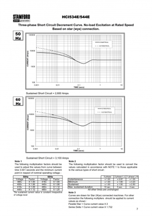
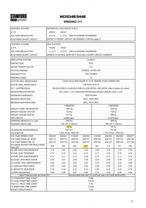
I have contacted a provider and got the specification of the alternator in their genset, images below of the fault current graph and the alternator per unit values.


I am looking into understanding what values to use. Am I correct in getting the sustained fault level and for an earth fault to apply the multiplication factor of 2.5 for sustained? I will make sure my disconnection times are less than the sustained maximum duration in order to not trip the generator breaker and loose all of the supply.


Alternator is 50Hz 415V
fc5681c638e7bada3947e466b96400fd-huge-newage-hci534e_1.jpg

3106a5e7994134e881a5487cbbe73194-huge-newage-hci534e.jpg


  • Unlike the street supply the output of a genset is a reactive impedance, and also a function of the state of load at the time of measurement. As a result, attempts to measure Zs in the normal way fail.

    To allow calculation, the wiggly curve is expressed as if it were a stair case with square corners, and flat regions.

    The results are given as multipliers, called by Cummins and others 'per unit factors' . So for example a genset configured for 100A, with a multiplier of 0.1, will supply 1000A into a dead short, until something changes.

    Typical multiplier values for gensets of some 100s of kVA or so are

    Sub-transient reactance X"d  0.09 – 0.17  First  6 cycles or so -determines maximum instantaneous current  and used for rating 'instant' breakers.

    Transient reactance X'd   0.13 – 0.20 6 cycles to 5 sec. current for short time delay circuit breakers.

    Synchronous reactance Xd 1.7 – 3.3 any time after 5 sec. This is the voltage droop, if there was no regulator to wind up the field and increase the torque and demand more fuel  i.e. woudl be the current without excitation support. In reality, the genset controller kicks in on this timescale.

    The Q factors are for  a step change in reactive load, and more use for determining the phase of the transients, and load steps for reactive loads.


    Your design current is 600kVA, 3 phase so I assume about 850A per phase L at full load.

    An LLL fault would heat the point of junction as if it was 2.5 times that.


    Your X'' d is 0.09. so an 11 fold multiplier into a dead short L-N , say 10kA , and then some more for luck, typically 2 for the worst case moment in the cycle to apply the short, as this gives an asymmetric transient.


    Your PSSC for rating your breakers could be 20kA.


    Is an LLL fault credible in your system ? If it is I'd consider checking if there are 'death or glory' fuses inside the genset.  three 1kA fuses would never go in normal operation, but would allow lower rated equipment downstream.


    However, what ADS is in the genset ? I'd expect the first item to limit the duration and let-through energy so that smaller (perhaps10kA) breakers can be used downstream.

    edit some background reading attached as an app note from Cummins.
  • Mike,


    Thanks for the explanation. My the confusion arises from the values and the graph.


    The steady state curve shows a 2700A 3- phase fault. if I use the reactance values shown the values are not consistent.


    Steady state 2700A -> For a LN fault x2.5 -> 2700 X 2.5 = 6750A

    Zero sequence reactance is 7% for A 600kVA unit. This gives around 11.9kA


    Am I missing something?


    Thanks,

    Mike
  • I'd like to think that you are not contemplating overloads or shorts of such duration that the quasi-steady state condition is ever reached before before the supply is automatically removed from the faulty section.


    Do you need to use some very long time delay breaker as the first device ?

    ADS needs to be sensibly fast, and I'd suggest that a few hundred mS would be enough to allow discrimination with final circuits on B and C type breakers.

    How many tiers of fuses and breakers do you have between the windings and the final loads, and how big is the system you are generating for ?

    In the absence of detailed design, a time factor of 3:1 between tiers is usually reliable for a first stab.( .i.e. 1sec/300msec/100msec/ near-instant  sort of thing for 4 layers)

    For normal operation stay below the rated KVA,  say 800A /phase or less, for sizing the main breaker I'd be assuming you'd be fast enough to use either X'd or X''d to estimate a PSSC, and the 2 figures are both close enough to being a multiply by ten for arm waving purposes.

  • Former Community Member
    0 Former Community Member
    On a 600kVA set, isn't your steady state around 800A - and as a first approximation of dividing by X"d of 0.09, would give you a fault current of around 8.8kA for a short duration (ie within the clearance time of the CPD)


    Which isn't that far away from Mike "multiply by 10" values (as you'd imagine) - for earth fault you really need to consider the use of symmetrical components and you'll require the zero sequence reactance of the machine.

    https://www.fecime.org/referencias/npag/ - try chapters 3, 4 and 5


    Regards


    OMS


  • Mike and OMS,


    I appreciate your values calculated and the fact that the full load current itself is pretty high, small MCBs will trip. What i am trying to do though is as everyone use Amtech. The Amtech platform has a set value for the generator fault level. As from the alternator manufacturer the fault curve is relatively flat towards the steady state I wanted to use this figure. I am sure this level will trip almost all devices despite that the installation is a 60+ yers old station with at least 4 levels of circuit breakers.


    What i found odd is that the calculated fault levels from the provided impedance per unit values do not really reflect the curve values. This is what I would like to understand.


    Thanks,

    Mike
  • I have a feeling that you have forgotten the poor old engine. The alternator fault levels are at infinite driving torque, but your average engine cannot provide this. The instantaneous fault level is controlled by the rotating mass (alternator and flywheel) but does not last very long (a few cycles at best). The front end CPDs of full generator rating will probably never open the circuit, even with a PPP fault (which is extremely unlikely). What will happen is the engine will stall as even at full torque it cannot support the virtually infinite torque required. Remember that engine torque at zero speed is nearly zero, and you only get sensible figures at somewhere near the normal operating speed. Engine maximum power output means exactly that, any overload which reduces speed also reduces the power available, so damage from short circuits is usually unlikely, whereas long sustained slight overload causes severe overheating.
  • Former Community Member
    0 Former Community Member
    The alternator fault levels are at infinite driving torque, but your average engine cannot provide this. The instantaneous fault level is controlled by the rotating mass (alternator and flywheel) but does not last very long (a few cycles at best). The front end CPDs of full generator rating will probably never open the circuit, even with a PPP fault (which is extremely unlikely). What will happen is the engine will stall as even at full torque it cannot support the virtually infinite torque required


    So, will the set have enough "whoomph" (technical term!) to be able to provide sufficient current for long enough to operate a protective device? If so in this example, will it operate an 800 A device? Or will it only be able to supply sufficient energy for long enough to operate say only a 100 A device? Or will it stall and shut down within your required disconnection time leaving the protective devices intact?


    Our conventional mains supply has a vast rotating inertia to provide enough "whoomph" to the extent it will not stall and carry on providing energy till something "gives"........ The conventional basis for tabulated disconnection times assumes this.


    Regards


    BOD
  • Thanks Dave and perspicacious, your responses seem reasonable to be honest, the table with the fault multipliers though has a time limit per fault type and for that I assumed that the time durations and levels corresponded to the alternator actually been driven by that diesel engine.


    Thanks

    Mike
  • Former Community Member
    0 Former Community Member
    If I've read the graph correctly, the set will provide just 2000 A at 0.1 sec. Will the preceding higher current be enough to operate the primary protective device and/or how far downstream? 


    Dare I mention RCDs?!


    Regards


    Bad BOD and Bed BOD till tomorrow
  • The main switchboard will be refitted with Micrologic 7.2 breakers with adjustable earth leakage and delay, I expect downstream all the final circuits breakers to disconnect before 0.4 (preferred instantaneously) seconds as per the regs. The Micrologics will be also set at before 0.4 seconds to provide backup. BS 7671 required the use of RCD at all final circuits when using a mobile generator not part of the fixed installation but that is not practical hence the Micrologics which are justified with a risk assessment. Once the job is done it is a matter of reconnecting the mains supply and turn off the earth leakage protection on the Micrologics without any breaker modification which is also fast.


    The main risk here is loss of supply on a main circuit supplied by the Micrologics in the case of insufficient fault current downstream of those breakers. Which eventually leads us to this whole story on the discrepancy of the fault graph and the per unit values. I also note that the per unit values provided have a time constant associated with them the sub-transient and transient values seem to not be useful as they are very fast.


    I also acknowledge that far final circuits will not cause a short circuit of such a degree to cause the current to raise above the overload current. In all the installation is safe, but just a matter of using the most suitable value when undertaking the calculations in Amtech


    Thanks,

    Mike