This discussion is locked.
You cannot post a reply to this discussion. If you have a question start a new discussion

Earthing neutral

Former Community Member
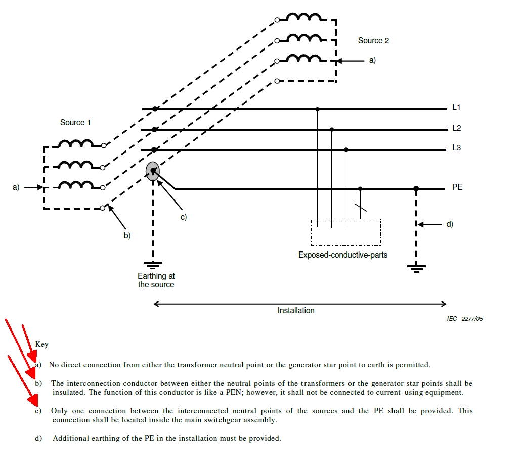
Why is it forbidden to earth the neutral at the source of a 3 wire system? 


  • It might - consider this rather simplified illustration - you will have to imagine the blackboard and the chalk...


    Imagine you are holding the bare PE, but your feet are in good contact with terra-firm earth, but outside the near field of the electrodes .

    Consider what happens when the TX faults HV phase to frame. The HV phase voltage goes down, and at the same time the HV and LV earth voltages at the fault

    both come up to meet it part way.

    The area of a circle a rod length or two around the electrode goes up a bit of course, but only the earth really near the electrode(s) rises to full fault voltage, then the volts slope off to almost nothing by 2 rod lengths radius. It is better with a large area mesh electrode of course.

    Let us assume the bit of ground you are standing on remains at or near 0V

    Ouch.


    Now repeat that thought experiment, but now with your hand on a similar PE with a mm or 2 of green and yellow stripy plastic between you and it. Not so much Ouch.

    The surge is still bad for kit further along the LV network of course, but the PE = CPC on the LV side is usually multiply earthed on the load side of things as it is bonded to water pipes and so on, so while the end near the transformer may rise to a few hundred V, the bit near the kitchen taps might only rise by a fraction of that.


    There is also a cultural/ historical aspect, as around here bare earth wires more generally are pre1966 , and is seen by many rather like cotton or rubber insulation, asbestos wadding, leadwork and various other things as indicating a "state of the ark"  installation, folk just do not expect to see bare wires for any function.
  • Former Community Member
    0 Former Community Member

    AJJewsbury:


    Again, I see no harm in multiple earthing of a PE.


    Because it's not just a PE in that diagram - it's also the system N - it ties the neutral points of both sources togther - and multiple earthing of a N can be a problem.


       - Andy.


    Not a PE in the diagram, but a PE in real life. I can not find or see any problems if earthing it multiple times.

  • Former Community Member
    0 Former Community Member

    mapj1:

    It might - consider this rather simplified illustration - you will have to imagine the blackboard and the chalk...


    Imagine you are holding the bare PE, but your feet are in good contact with terra-firm earth, but outside the near field of the electrodes .

    Consider what happens when the TX faults HV phase to frame. The HV phase voltage goes down, and at the same time the HV and LV earth voltages at the fault

    both come up to meet it part way.

    The area of a circle a rod length or two around the electrode goes up a bit of course, but only the earth really near the electrode(s) rises to full fault voltage, then the volts slope off to almost nothing by 2 rod lengths radius. It is better with a large area mesh electrode of course.

    Let us assume the bit of ground you are standing on remains at or near 0V

    Ouch.


    Now repeat that thought experiment, but now with your hand on a similar PE with a mm or 2 of green and yellow stripy plastic between you and it. Not so much Ouch.

    The surge is still bad for kit further along the LV network of course, but the PE = CPC on the LV side is usually multiply earthed on the load side of things as it is bonded to water pipes and so on, so while the end near the transformer may rise to a few hundred V, the bit near the kitchen taps might only rise by a fraction of that.


    There is also a cultural/ historical aspect, as around here bare earth wires more generally are pre1966 , and is seen by many rather like cotton or rubber insulation, asbestos wadding, leadwork and various other things as indicating a "state of the ark"  installation, folk just do not expect to see bare wires for any function.


    Of course, you have a resistive divider- the PE during the HV fault is 3,175 volts to remote earth on an 11kv solidly grounded Y system. So the options are either rapid disconnection of the HV supply (few cycles tops) or impedance earthing of the HV neutral (X0) at the substation.


    Granted inside the building this is less of an issue with bonding bringing everything to the same potential, but if you are outside with a tool then you are referenced to remote earth.


    One can separate the HV and LV neutral- sure- but what happens if HV crosses into the LV? How do we know the earth electrodes on the LV side will facilitate fast enough operation of an HV device? Yes we can measure a stable 5 or 1 ohm on an earth electrode, but after 10 years said electrodes may be 500 or more ohms. 


    Therefore, it is seen advantageous to interconnect the HV neutral with the LV neutral guaranteeing a low impedance path.


    Of course- we can leave them disconnected.


    BUT- why couldn't I earth the neutral 40 feet away once beyond the sphere of HV earth rod influence? Why if I install a paralleled peak shaving generator as my second source must I run an insulated neutral to the Y point?


    I'm going to be frank, but the diagram seems to be based around a 230/400Y system... not considering a true line to line system. 133/230Y is rare in Europe, and where present is going to 230/400Y. Probably why the disconnection times for Uo 121 volts to 230 volts are the same. 


    Of course, BS7671 may know something here.

  • I suspect you are quite right - the IEC docs will be based on 230/400  practice; 690v 3 phase is much rarer, being really confined to larger factories, as mines and off shore do their  own thing and the only time you see 110v is on a UK building site where it is centre tap earthed so really 55-0-55, and the rest of  the continentals look at us funny when we do that. (and having worked in Germany I can say they do that on some other occasions too.?)


    I suspect the thinking is the all final user 3 phase supplies that are wired as star could potentially at some point be made 4 wires from 3, and need treating accordingly the same. (I have seen factory kit with only the 3 phases supplied, no neutral so a 230V stolen between 1 phase and earth for example, it is not really permitted, but if it happens you do not want it to make the system dangerous.)


  • Not a PE in the diagram, but a PE in real life. I can not find or see any problems if earthing it multiple times.


    But it not just a PE, even in real life it's also a N - it's liable to be carrying current in normal service - even if in this case of not distributing N to the loads it'll still be carrying circulating currents. Remember that comment that it should be thought of as 'similar to a PEN'?


       - Andy.
  • Former Community Member
    0 Former Community Member

    AJJewsbury:


    Not a PE in the diagram, but a PE in real life. I can not find or see any problems if earthing it multiple times.


    But it not just a PE, even in real life it's also a N - it's liable to be carrying current in normal service - even if in this case of not distributing N to the loads it'll still be carrying circulating currents. Remember that comment that it should be thought of as 'similar to a PEN'?


       - Andy.


    Where is that current coming from though? Are circulating currents really that bad in magnitude? Keep in mind they are not regulated nor restricted in TN-C-S which in theory would produce parellel current in orders of magnitude more.


    Mandating an insulated neutral would force 5 wires if the HV neutral must be tied into the LV neutral. 


    What about a wye-wye connection?


  • Where is that current coming from though? Are circulating currents really that bad in magnitude? Keep in mind they are not regulated nor restricted in TN-C-S which in theory would produce parellel current in orders of magnitude more.


    I don't have the experience to know what sort of magnitude circulating currents might be considered normal in a parallel source situation - maybe some of the 'big boys' here might be able help?


    I might hazard a very wild guess that they're likely to be small percentage of the normal load - so maybe 1-10A for a 1000A system? Certainly something inconsequential thermally, but even a few amps can be significant if a break in a c.p.c. means you're passing it through a couple of separate electrodes to complete the circuit. Say both electrodes were 20 Ohms (the traditional BS 7430 requirement for LV electrodes) and 2A flowing between them would raise each of them by 40V and so could have 80V across the break between the two parts of the system - which probably isn't comfortable from a shock protection point of view.


    With an uninsulated conductor you've also got the issue of the N current flowing through exposed- and extraneous-conductive-parts in parallel to the intended conductor - which again even if its only a few amps can be unwelcome from an EMI point of view - and just the sort of situation that specifying a TN-S system over a TN-C-S one is meant to avoid.


      - Andy.
  • Former Community Member
    0 Former Community Member

    AJJewsbury:


    Where is that current coming from though? Are circulating currents really that bad in magnitude? Keep in mind they are not regulated nor restricted in TN-C-S which in theory would produce parellel current in orders of magnitude more.


    I don't have the experience to know what sort of magnitude circulating currents might be considered normal in a parallel source situation - maybe some of the 'big boys' here might be able help?


    I might hazard a very wild guess that they're likely to be small percentage of the normal load - so maybe 1-10A for a 1000A system? Certainly something inconsequential thermally, but even a few amps can be significant if a break in a c.p.c. means you're passing it through a couple of separate electrodes to complete the circuit. Say both electrodes were 20 Ohms (the traditional BS 7430 requirement for LV electrodes) and 2A flowing between them would raise each of them by 40V and so could have 80V across the break between the two parts of the system - which probably isn't comfortable from a shock protection point of view.


    With an uninsulated conductor you've also got the issue of the N current flowing through exposed- and extraneous-conductive-parts in parallel to the intended conductor - which again even if its only a few amps can be unwelcome from an EMI point of view - and just the sort of situation that specifying a TN-S system over a TN-C-S one is meant to avoid.


      - Andy.


    From my view point I don't see multiple parelled sets of 4/0 PE breaking at once. Considering all the PME supplies... 


  •  


    From my view point I don't see multiple parelled sets of 4/0 PE breaking at once. Considering all the PME supplies... 


    Is "4/0" a reference to AWG? About 100mm²?


    Perhaps not, but I don't think there's anything in the digram that suggests the size of the system or that conductors are to be paralleled - it could just as easily be applied to a small system - say a domestic off-grid setup with multiple sources where perhaps something closer to single 1.5mm² conductors might be the order of the day.


       - Andy.


  • Attached files


    Actually your diagram is a little different to the one in BS 7671 (in appendix 9) - I'm guessing yours is the IEC original and the one in BS 7671 has been 'modified by committee'. Does yours have a title or description that refers to the Earthing system?


    The BS 7671 ones - both with a distributed N (Fig 9A) and without (9B) appear identical in earthing arrangements (TN-S to my eyes) but in BS 7671 9A is tagged TN-C-S and 9B TN.  I wouldn't have put it passed the UK committee/typesetters to have got things confused - they seem to have replaced the note/key references (a) to (d) with (1) to (4) so they don't match the diagrams any more.


      - Andy.