This discussion is locked.
You cannot post a reply to this discussion. If you have a question start a new discussion

Switched alternative to public supply. Tesla Powerwall and gateway. Have I got this right?

Who here has first-hand of Tesla Powerwall? On cursory inspection, on-line technical info is sparse.


One of my regular domestic customers has had a quote for a Tesla Powerwall, including the Tesla isolating gateway to allow some property consumption in selected backup circuit(s) during network outage. Meanwhile I am quoting for CU upgrade to go in ahead of that work so that it can take place. The latter is basic work, no problems, were it not for the former which is providing me with a bit of a conceptual challenge. Now the first bit below is second-hand from the Tesla installer via my customer. Hence parts of it might be lost in translation, but as far as I have received from Tesla installer:


"Go ahead and to the CU, - it won't affect the Tesla."

The Tesla gateway contains SPD so I "don't need" to fit SPD in my CU. (But Tesla only up to 1KV, so not fully meeting AFAICT, 442.2.2)

Now the biggie: Tesla say they will be fitting a separate earth rod such that (as far as I understand it..), when the gateway entirely disconnects the network including earthing conductor (which after the supply head is no longer PEN 461.2).. then the gateway  "islands" the whole property on the TT via it's switch 537.1.5. 551.6 .


I'm not so familiar with switched alternative to public supplies, and in the absence of anything from Tesla, those who are able to might add to my reasoning below (or otherwise abuse it):


1) The property bonding and MET would still be connected to incoming PEN via gas/water pipe and next-door house(s).

2) What happens to the Tesla earth rod in normal (grid connected) operation? I'm guessing it's wired by the installer such it's effectively just a bonded extraneous conductive part. 

3) Under loss of network power, Tesla gateway disconnects incoming supply and TNCS earthing conductor and now floats on the parallel impedance of it's Ra and the bonding. During this time,the disconnected property would (due to high-ish Ra) likely get bootstrapped close to whatever voltage is on the incoming gas/water/bonding.

4) Although there are two earthing systems, there aren't two simultaneously accessible earthing systems..  Because in normal (network) use the TT electrode would be just a bonded extraneous part, and in "island" mode the TNCS earthing is not connected, - But to make this claim, we'd then need to also state that the TNCS "not-MET" (with installation earth no longer connected) was a bonded extraneous conductive part. 

5) Loss of PEN externally: The Tesla I'm guessing would detect any possible lift in earth potential of the TNCS MET and could then switch into a safe condition (house disconnected entirely, other than bonding to PEN), and un-powered, or even maybe continue to generate for the house backup circuits, while floating on whatever fault condition PEN/bonding voltage was imposed on it. 

Have I reasoned this out right? 


  • Former Community Member
    0 Former Community Member
    On cursory inspection, on-line technical info is sparse


    Last time I did the calculations using their figures of capacity, charge/discharge cycles over lifetime, the "free electricity" you have stored costs you 45p/kWh to get it out to use.............


    You must be green (both definitions!) to go for it.


    Regards


    BOD

  • justinneedham:

    Who here has first-hand of Tesla Powerwall? On cursory inspection, on-line technical info is sparse.


    One of my regular domestic customers has had a quote for a Tesla Powerwall, including the Tesla isolating gateway to allow some property consumption in selected backup circuit(s) during network outage. Meanwhile I am quoting for CU upgrade to go in ahead of that work so that it can take place. The latter is basic work, no problems, were it not for the former which is providing me with a bit of a conceptual challenge. Now the first bit below is second-hand from the Tesla installer via my customer. Hence parts of it might be lost in translation, but as far as I have received from Tesla installer:


    "Go ahead and to the CU, - it won't affect the Tesla."

    The Tesla gateway contains SPD so I "don't need" to fit SPD in my CU. (But Tesla only up to 1KV, so not fully meeting AFAICT, 442.2.2)

    Now the biggie: Tesla say they will be fitting a separate earth rod such that (as far as I understand it..), when the gateway entirely disconnects the network including earthing conductor (which after the supply head is no longer PEN 461.2).. then the gateway  "islands" the whole property on the TT via it's switch 537.1.5. 551.6 .


    Would it be "TT"? I would think that the system will go TN-S in island mode? At least that's what the IET Code of practice for electrical energy storage systems recommends. The earth electrode is required to comply with Regulation 551.4.3.2.1, and not necessarily to form a "TT".


    Island mode (see BS HD 60364-8-82) is NOT associated with "TT island" as often used by the EV charging community ... which is why I really disagree with the use of the term "TT island" which does NOT appear in any of the standards, or indeed the IET guidance.


    I'm not so familiar with switched alternative to public supplies, and in the absence of anything from Tesla, those who are able to might add to my reasoning below (or otherwise abuse it):


    1) The property bonding and MET would still be connected to incoming PEN via gas/water pipe and next-door house(s).


    This is the reason the system will go TN-S when in island mode. It's also the reason you can't easily generate a TT system in island mode.


    2) What happens to the Tesla earth rod in normal (grid connected) operation? I'm guessing it's wired by the installer such it's effectively just a bonded extraneous conductive part. 


    It is nothing other than an extraneous-conductive-part in connected mode, although if the resistance is low enough it may help keep touch voltages down, on exposed-conductive-parts, or extraneous-conductive-parts, that are accessible outdoors, particularly away from the main building(s), in the event of a failure of the PME neutral conductor.


    3) Under loss of network power, Tesla gateway disconnects incoming supply and TNCS earthing conductor and now floats on the parallel impedance of it's Ra and the bonding. During this time,the disconnected property would (due to high-ish Ra) likely get bootstrapped close to whatever voltage is on the incoming gas/water/bonding.


    Is this the case? The recommendation of the IET CoP are to leave the distributor's means of earthing connected, but to isolate the Live Conductors of the supply.


    4) Although there are two earthing systems, there aren't two simultaneously accessible earthing systems..  Because in normal (network) use the TT electrode would be just a bonded extraneous part, and in "island" mode the TNCS earthing is not connected, - But to make this claim, we'd then need to also state that the TNCS "not-MET" (with installation earth no longer connected) was a bonded extraneous conductive part. 


    To separate them would require a suitable distance below ground of all parts connected to the PME, and everything connected to the TT system. This is in practice in most domestic premises at least, not achievable, not least because of extraneous-conductive-parts, hence the recommendation to leave the distributors means of earthing connected, and to isolate the live conductors (each L, and N). N isolated to prevent two N-E bonds, which causes all sorts of havoc, although I fully appreciate that technically it remains connected via the means of earthing.


    5) Loss of PEN externally: The Tesla I'm guessing would detect any possible lift in earth potential of the TNCS MET and could then switch into a safe condition (house disconnected entirely, other than bonding to PEN), and un-powered, or even maybe continue to generate for the house backup circuits, while floating on whatever fault condition PEN/bonding voltage was imposed on it. 


    Not sure of that ... unless it contains a means of detection according to 722.411.4.1 (iii) of either BS 7671:2018 or BS 7671:2018+A1:2020.


    Have I reasoned this out right?


    Perhaps not?
  • Ignoring the uncertain financial arguments for buying the thing,  which may well benefit from a cool headed re-visit, a large battery, a charger for the same and an inverter in a box has similar  requirements electrically   to  any back up generator of the kind that can also be paralelled with the mains supply.

    An earth electrode does not a TT installation make, if the genset is connected to  a system with a CPC - it is just TN-S, only when you are the generator, not the local substation you have to have the earth electrodes and NE links that a substation and or the DNO wiring would normally provide. This is because it is quite possible that a loss of supply may mean loss of CPC function and loss of NE bond as well, depending which bit of the DNO wiring has been hit by an enthusiastic digger bucket.


    I am quite sure that when islanded  the powerwall does have a metallic connection to the house wiring CPC, and if you'd like MCBs and RCDs to work, there had better be an NE link switched in as well.


    Now ignoring the 2nd hand advice, I'd say having a system where you wish to load shed when on inverter really does affect the CU layout, unless there are to be lots of downstream contactors on individual loads, as it becomes more like an economy 7 rig - either 2 CUs or a contactor and a split one.

    If your new CU feeds a mix of sockets to be kept on, and ones to be dropped, from the same final circuit, that will make it very difficult in practice to achieve the separation required.
  • I too am unhappy with disconnecting the earthing system from the mains supply. To make this work you need to ensure that all the extraneous conductive parts are isolated from outside the property with insulated sections or whatever, and it would probably best not to main bond anything as a result, so that there cannot be a danger from external potentials. It would appear that if this is just for backup, 2 CUs will be needed, one before the Tesla switch and one after, but the installer just expects to connect the whole house. Good luck with that as really you need to install a complete new network of backed up sockets and lights. All very expensive!


    I cannot see why anyone should buy one of these products, simply because we do have continuous electricity supplies and the life of lithium batteries so far has proved to be 500 - 1000 full cycles if you are lucky. That might be OK in a car (100,000 miles say), but it is probably only 3 years if you really want to make use of your solar electricity. It will be interesting to see how long these batteries last, and Tesla may well have a better product than those from elsewhere, but I would rather not take the risk from lots of experience with batteries for broadcasting etc.
  • Thank you , I'll chew on all those comments over the next day or two.. busy now..Rgds


  • davezawadi:

    I cannot see why anyone should buy one of these products, simply because we do have continuous electricity supplies and the life of lithium batteries so far has proved to be 500 - 1000 full cycles if you are lucky. That might be OK in a car (100,000 miles say), but it is probably only 3 years if you really want to make use of your solar electricity. It will be interesting to see how long these batteries last, and Tesla may well have a better product than those from elsewhere, but I would rather not take the risk from lots of experience with batteries for broadcasting etc.



    The trick is to never allow a full cycle on the battery. It's not a Tesla Powerwall, but I have a modest little battery bank in my loft.  The battery is rated at 3.3kWh.  But the battery management in the inverter will not let me use more than 3.0kWh.  The battery is supposed to last 10 years, though its capacity will gradually reduce over the years.


    Two things particularly wear out a LiIon battery: running them flat, and fast charging up to a full 100% charge.
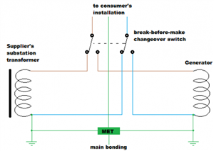
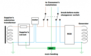
  • If it helps at all, here are some diagrams (originally done for the old Forum) for the usual layout for switched alternative local generation (the principle is the same whether it's a petrol generator, or battery and inverter, or anything else).


    The first one shows the simplest case of everything TN-S - and how the generator is configured/earthed in just the same way as the DNO supply in a nice symmetric layout. When connected to the DNO's supply (and the generator off), the DNO's electrode provides the means of earthing and the local generator's earth electrode is nothing more than one more extraneous-conductive-part. When the DNO supply is off and the generator running, the local rod provides the means of earthing and the DNO's earthing system is just another extraneous-conductive-part as far as the installation is concerned.

    4ff306a9c315f8f85ae1c8c871974c2f-huge-generatorbasictn-s_zps3cec182e.png


    Then what you're more likely to have in practice, with a PME supply and an RCD very soon after the generator (as most small generators/inverters won't be able to produce the large currents needed to open overcurrent devices for ADS) - so some of the symmetry is lost, but the underlying principle is the same:
    836149818d0b42fd1738c67a374ee52f-huge-generator-detail-tn-c-s-zps660b2d3f.png


       - Andy.
  • This is all worthwhile. Thank you.. 

    Skipping over for the moment the practicalities of the system.


    Graham writes "I would think that the system will go TN-S in island mode? At least that's what the IET Code of practice for electrical energy storage systems recommends. The earth electrode is required to comply with Regulation 551.4.3.2.1, and not necessarily to form a "TT". 

    - I will buy the COP, but before I receive that. You imply TN-S? This and all the adjacent properties being TNCS right now. Even if it were connected TN-S at the supply head, it would more-or-less be TNCS via the neighbours bonding to the gas.


    Mike writes "having a system where you wish to load shed when on inverter really does affect the CU layout.., "

    Indeed yes.  I didn't want to complicate my original post on this, but that's something else on the list for my customer who wants this facility but doesn't necessarily understand the considerable potential for extra wiring complexity.


    I will add a final twist.. The Customer has an early-adopter EV charger also. Installed when external use on TNCS still had the "reasonably practicable"  get-out in 17th edition. The unit is fitted just inside up-over garage door, alongside the consumer units, and is exclusively used outdoors, cable under the swing-door. Customer has suggested pulling the EV charger into the new CU.. all very well, but I've turned this down since I can't fulfill the need for a fully isolated TT. Meanwhile I'm told that Mr Tesla has suggested "fixing" the problem by connecting it to "his" new rod, - This not quite worked out comment is where my original puzzle came from.

    If Tesla is serous, then this is either:

    A) Implying that the new rod is separate from the incoming earth in his installation, yet to use it and connect the EV charger would be ignoring inevitable proximity to the alternative supplier earthing system. Non starter then on two counts, because we've discounted the former (rod is connected to the PME) and the latter (proximity of two earthing systems).

    ..or B) The new rod will miraculously meet Annexe A733.3 for 70V touch voltage. - Not a chance in hell.


    I am going to conclude that Tesla might be a little unclear about things in that respect, - or this is Chinese whispers playing havoc.

    Plan:

    Don't do anything about the EV charger- leave it alone on it's existing CU, because I can't change it at all without replacement with a fangled one having monitoring device 722.411.4.1(iii).

    Issue relevant text about the above.

    Find out if customer really wants backup circuits and if so to spell that out to me ASAP.

    Fit new CU (with or without second backup circuits CU), and let Tesla get on with their bit.


  • Having downloaded and read the installation instructions for a powerwall unit, I note they are very US centric, and the 220V model almost expects to be wired split phase, except at the last moment,  a note says to ground one side. That will be an NE link - essential when running on inverter, and expressly prohibited in UK law when running off the mains.

    Now the US do not have TNS or TT, at least not in the form we recognise, so I suspect the nuances of a UK system may not have been apparent to the original designers.

    The result, if the instructions are to be followed to the letter is  not esqr compliant. Now it may be that there is some extra bit of instruction  that UK installers know that is not in the online info, but I can well imagine a sales and help line just parroting the US style advice without too much thought.

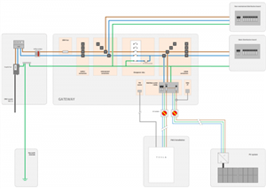
    The wiring diagram below reproduced from this UK website  makes more sense, and has a clear NE link


    5af961f7fcd2668fd6ca36028c62ce87-huge-powerwall-circuit-diagram.png


  • justinneedham:

    This is all worthwhile. Thank you.. 

    Skipping over for the moment the practicalities of the system.


    Graham writes "I would think that the system will go TN-S in island mode? At least that's what the IET Code of practice for electrical energy storage systems recommends. The earth electrode is required to comply with Regulation 551.4.3.2.1, and not necessarily to form a "TT". 

    - I will buy the COP, but before I receive that. You imply TN-S? This and all the adjacent properties being TNCS right now. Even if it were connected TN-S at the supply head, it would more-or-less be TNCS via the neighbours bonding to the gas.


    Since consumers are not generally permitted to combine N & E functions in a single conductor in their installations according to ESQCR, the arrangement in island mode can only be described as TN-S.


    However, as you correctly point out, the arrangement will remain connected to the PME earthing system (but this may well be the case anyway because of extraneous-conductive-parts). Therefore, certain provisions regarding the use of the PME earthing terminal continue to apply to the installation in island mode as well as connected mode.


    Mike writes "having a system where you wish to load shed when on inverter really does affect the CU layout.., "

    Indeed yes.  I didn't want to complicate my original post on this, but that's something else on the list for my customer who wants this facility but doesn't necessarily understand the considerable potential for extra wiring complexity.


    This is also discussed in the IET CoP.Ultimately the easiest approach may well be two CUs, one with "connected mode only" loads, and the other which is energized in both connected mode and island mode.


    I will add a final twist.. The Customer has an early-adopter EV charger also. Installed when external use on TNCS still had the "reasonably practicable"  get-out in 17th edition. The unit is fitted just inside up-over garage door, alongside the consumer units, and is exclusively used outdoors, cable under the swing-door. Customer has suggested pulling the EV charger into the new CU.. all very well, but I've turned this down since I can't fulfill the need for a fully isolated TT. Meanwhile I'm told that Mr Tesla has suggested "fixing" the problem by connecting it to "his" new rod, - This not quite worked out comment is where my original puzzle came from.

    If Tesla is serous, then this is either:

    A) Implying that the new rod is separate from the incoming earth in his installation, yet to use it and connect the EV charger would be ignoring inevitable proximity to the alternative supplier earthing system. Non starter then on two counts, because we've discounted the former (rod is connected to the PME) and the latter (proximity of two earthing systems).

    ..or B) The new rod will miraculously meet Annexe A733.3 for 70V touch voltage. - Not a chance in hell.


    Agreed here - the earth electrode resistance will be tricky.


    An alternative approach may be to use an open-PEN detection device. HOWEVER ... there are some tricky nuances here also:


    • A device as described in 722.411.4.1 (iii) could be used, but for a single-phase installation a measurement earth electrode will be necessary. The measurement earth electrode would have to be separated by at least 2 m below ground from any buried uninsulated conductive parts connected to the PME earthing system. I know of at least one product of this type.

    • A device as described in 722.411.4.1 (iv) would be ineffective in island mode. However, unless the car is being used as part of the island mode power supply, would you want the car to remain connected? You certainly couldn't charge it fully unless you had very large storage batteries in your EESS. So therefore the vehicle could be "electrically disconnected" (L, N and PE) in island mode. There may also be some voltage issues in connected mode in installations with solar PV inverters (and perhaps connected mode EESS inverters) causing nuisance tripping.

    • If you are using a device the manufacturer claims complies with 722.411.4.1 (v), you will be reliant on that manufacturer's guidance for using it in an installation with EESS.


    These issues are discussed in the forthcoming IET CoP for EV Charging Equipment Installation, 4th Edition, which is available to pre-order and is due to be available before 1 April 2020.


    I am going to conclude that Tesla might be a little unclear about things in that respect, - or this is Chinese whispers playing havoc.

    Plan:

    Don't do anything about the EV charger- leave it alone on it's existing CU, because I can't change it at all without replacement with a fangled one having monitoring device 722.411.4.1(iii).


    You could argue it complied with an earlier version of BS 7671, and you've not made things worse.


    Issue relevant text about the above.

    Find out if customer really wants backup circuits and if so to spell that out to me ASAP.


    Backup of all circuits isn't really practicable - probably not recommended by Tesla either?


    Fit new CU (with or without second backup circuits CU), and let Tesla get on with their bit.


     Agreed