This discussion is locked.
You cannot post a reply to this discussion. If you have a question start a new discussion

EV CHARGING EQUIPMENT

I am hearing from my network of contractors, that have actually read the new 722, that they have been asking charging equipment manufactures for documentary proof to comply with Note 5 of 722.411.4.


They are getting knocked back for asking or in one case a Declaration that says the particular device complies with BS 7671. I think that is wrong to declare that as BS 7671 is an installation safety standard and not a product standard. I believe that as a minimum the equipment must comply with the Low Voltage Directive and be CE marked. I also believe that manufacturers have to issue a Declaration of Conformity. 


BS 7671 722 has numerous references to the various standards required such as BS EN 61851 that the equipment must comply with. I am thinking it may be illegal to offer the sale of equipment that does not comply with the Low Voltage Directive and is not CE marked?


I am hoping the countries top man of equipment safety standards, Paul Skyrme , sees this post and will come on and give us his expert view?


Has any forum member asked for a Declaration of Conformity from EV charging equipment manufacturers and received one?
  • Andy


    Yes I have done that but that is Line to earth.
  • 095a3a5017d303e18d6880604521b152-huge-55cb8651-471c-4290-a32a-9b3e1fa4ebfa.jpg


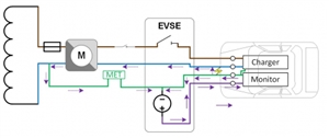
    I had the diagram that Graham Kenyon posted in another discussion in mind.

    https://communities.theiet.org/discussions/viewtopic/1037/25732?post_id=138070#p138070


    Andy B.
  • Dave, thanks for that, but  I am a little puzzled by your units

    DC + 18ms and DC - 7.5ms. So all passed with flying colours, trip times about 20ms at 30 mA all round. 10 MA of DC changed the AC 180 to 21 mA and DC+ to 12 mA


    Are these ramp tests, results in mA RMS at time to trip, or times in milliseconds ?

    Either could make sense in the context but imply subtly different things.


    In  any case I am heartened that you too see the blinding current is comparable to the trip current , as that backs up my observations - so 20mA may pull a 30mA RCD slightly off beam on a 30mA test, but it will still fire at a fault current of 100mA, and still needs a jammer comparable to the higher test current to blind it.


    The failure to trip on a supply with a PSSC of <16 amps, tells me this is an electronic RCD and internally there is a fairly chonky actuator coil pulled in by a power transistor or triac, not a delicate hairspring loaded mechanical balance. The actuator current needed to fire ones of this sort can be several amps, and the internals are not as fine or as fussy as the traditional passives.


    Please take care not to burger what looks like a decent PSU, - note that at the moment of opening, you do not know if the L or N arc extinguishes first, so there is a risk of a mains voltage or part of it appearing on the PSU for a short time if the contact with the PSU accross is the one that opens first.

    Also,  even with the volts low, you are shunting the N sense coil with the unknown output impedance of the PSU - which should be quite low and may give some imbalance to begin with.


    If there is a known series resistance, say 100 ohms,  (even an old kettle element or something would do) then the fault current if subjected to mains is limited, and the current share between coil and PSU is very much in favour of the coil at a few milli-ohm versus the PSU and resistor combo.


    I have also spoofed an LNE with a fake E and a very local NE bond for such tests, from an L and N only - so upstream RCDs are not affected. But of course only after double checking polarity is right.


    Perhaps I too need to take a pic, but my set  up is, shall we say, rather more agricultural, and I'd want to tidy up first, or folk will chitter about the exposed live bits.


  • You are right Mike that should be mA not ms in the first paragraph, typical first draft I am afraid. I didn't mention another interesting thing either, and that is that switching the DC on, or resetting the RCD with it on also usually causes another trip, as the current edge obviously causes an inbalance and fires the mechanism. I need to find some other makes of RCD, I have never taken one of this type apart although have used a lot, and have found them particularly reliable. As far as the PSU goes, as there is no load and I put the PSU in the neutral connection there is also no mains voltage difference. The Megger obviously applies the live to earth to get the fault current, and so there is no great danger. Also the PSU is pretty robust anyway, with some capacitance across the outputs, so I don't expect trouble. The only problem I have had with one of these was due to battery charging for long periods at maximum output, the output current sense resistor changed value upwards making the meter reading and current limit rather unsatisfactory (and only 6A too into a 100AH battery so connected a long time). These RCDs are comparatively cheap and from China (isn't everything) and may be from the same factory as some other makes, they are a massive player in the market.


    Looking at the results it appears that this type would be fine in a car charging point, there is not a DC problem at 20mA, and they are more than fast enough to give excellent protection although supposedly "only" to 61008-1.

  • Sparkingchip:
    095a3a5017d303e18d6880604521b152-huge-55cb8651-471c-4290-a32a-9b3e1fa4ebfa.jpg


    I had the diagram that Graham Kenyon posted in another discussion in mind.

    https://communities.theiet.org/discussions/viewtopic/1037/25732?post_id=138070#p138070


    Andy B.


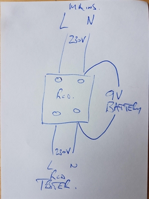
    All we need to simulate that scenario is a battery and two bits of wire.
    8da6e58ead4d00263811369f76734aab-huge-20200410_103726.jpg

    If you have a multimeter and some resistors to hand you elaborate it a bit, but in essence isn't that the scenario?


    Andy Betteridge 

  • Yes Andy, but that will put the short circuit ability  (which may be an amp if its a good battery) through the RCD and we are working on milli-amps of DC! A 1k resistor also in the battery circuit will give 9mA etc.

  • davezawadi:

    Yes Andy, but that will put the short circuit ability  (which may be an amp if its a good battery) through the RCD and we are working on milli-amps of DC! A 1k resistor also in the battery circuit will give 9mA etc.


    Agreed - that's effectively what we have with EV charging equipment pilot, but the source is 12 V not 9 V.


    How much is shared with the Neutral depends on the resistances of the conductors upstream back to the point of common coupling.


    Therefore in a TT system, the risk is less than a TN system, and TN-S lower DC current is likely to be shared than in a TN-C-S (PME) installation.


  • gkenyon:


    davezawadi:

    Yes Andy, but that will put the short circuit ability  (which may be an amp if its a good battery) through the RCD and we are working on milli-amps of DC! A 1k resistor also in the battery circuit will give 9mA etc.


    Agreed - that's effectively what we have with EV charging equipment pilot, but the source is 12 V not 9 V.


    How much is shared with the Neutral depends on the resistances of the conductors upstream back to the point of common coupling.


    Therefore in a TT system, the risk is less than a TN system, and TN-S lower DC current is likely to be shared than in a TN-C-S (PME) installation.


     Hi Graham. I thought I would share the reply I got from Mitsubishi regarding the "granny lead" that came with the car which I mentioned earlier in this thread;


    Good morning,

    Here’s a brief explanation of what the CCID box does and how it controls the charging. We have no information as to what type of RCD is fitted to the CCID.

    The box on the cable is not the charger, it is a control and interruption device that switches the current to the on board charger (OBC) which is mounted in the car, on and off. The CCID initially outputs a 12VDC supply via a switch onto pin 3 of the EVSE (Electric Vehicle Supply Equipment) Connector whenever the charge lead is  plugged in to a 240VAC power supply. This indicates the EVSE is ready, but not connected to a vehicle.

    When the EVSE connector is connected to a vehicle, a resistor in the OBC pulls the voltage on pin 3 down to 9V. This indicates to the CCID that it is connected to a vehicle. At this point, the CCID activates a switch to start sending the PWM Pilot signal out on Pin 3. The pilot signal tells the OBC how much current it can draw. In the UK this will be 10A.

    Once the OBC registers the Pilot signal, it switches on another switch. This connects a resistor into the circuit which pulls the voltage down to 6V. This tells the CCID to commence charging and the CCID will then switch on the RCD to allow mains supply to the charge lead.

    When the battery has reached full charge the OBC will turn off the relevant switches which puts the pilot signal back up to 9v which tells the CCID to switch off the RCD.

    I hope this helps.

    Kind regards,


    We have no information about the RCD in the CCID, but if it is double pole, then from the above the neutral would only be connected when 6V were showing in the DC circuit. Regardless of whether the RCD was DP or not, the whole of the time the vehicle is charging, only 6V would be on the circuit. 


  • OK, but:


    1. The charging cable is Mode 2 not Mode 3 or 4. The two can't be 100 % compared. This is why the requirement for Type B (or Type A or F + RDC-DD) is where the vehicle connector is used, for tehthered cables or Mode 3 / 4 charging station. With Mode 3, there are additional options available for the pilot. Where you have Mode 2 cable, a Type A RCD is sufficient.


    2. When the vehicle is not connected, or if there is a problem in the monitoring circuitry on the vehicle, the source is 12 V. Therefore with a tethered cable on Mode 3 (or EVSE where the cable is left plugged in), we still have the situation that an N-E fault on the cable, which can happen at any time, provides 12 V DC. And the cable is connected at all times.


    I would recommend, if you want to look into this further, to have a look at BS EN 61851-1 (or IEC 61851-1). Quite a lot of areas' library subscriptions will permit you to have a look at the standard on line, although I'm sure the resourceful individual could perhaps find a way to access on the internet in any case.


    I've also seen a number of articles on web-sites about the vehicle charging interface, where the diagrams and info in BS EN 61851-1 (IEC 61851-1) are reproduced.
  • OK you say what if a N-E fault occurs on the cable or elsewhere in car or charger. This will trip any RCD as a large current (compared to 30mA) will be diverted to the earth conductor, bypassing the N side of the RCD. The small DC signal (lets say 12 mA or whatever) will not prevent this trip. In any case to be dangerous we need a second fault, say a lost N elsewhere and a person effectively connected to ground touching exposed conductive parts of the car. Under the same conditions I can see that a large number of consumers will be exposed to exactly the same danger in many other situations. The danger will be a bit more if the car has finished charging but is still connected, but under this condition we still need a fault and a person well connected to ground, whatever the RCD does.


    It seems to me that this is getting out of proportion as it is not possible to avoid any risk without making cars class 2 which seems to be unacceptable to "the powers that be". The supposed solution is not available to be risk free, RCD or not. Because the car body cannot be isolated from the supply system (even if the supply is TT, and that is a severe problem in urban environments) we have some level of risk from faults. Such faults are very unusual (when did you last find an appliance with a N-E fault in the connecting cable?) and it is probably folk law that RCD tripping in the presence of a high fault current is prevented by 12mA of DC, although the 30mA value may be somewhat increased. It seems to me that the RCD reliability is probably less good than the cable fault scenario, and so we are not making any difference with increased complexity.


    I cannot find a type B RCD in my odds box to evaluate it properly. A loan of one would be much appreciated if anyone near Bristol has one hanging about (working condition!) or would post it to me.

    Thanks