This discussion has been locked.
You can no longer post new replies to this discussion. If you have a question you can start a new discussion

Can Zs at DB ever be less than the Zs of the feeding circuit?

Former Community Member
I am reviewing an EICR recently issued for a building with several Distribution Boards feeding sub-Distribution Boards.

I have noted that in some instances, the figure recorded for 'Zs at this board' is significantly less than the Maximum Measured Zs for the circuit recorded on the feeding DB.

e.g. DB FF4 is recorded as being fed from DB FF1.  The feeding circuit to DB FF4 is recorded as having a Maximum measured Zs of 0.4 Ohm, but the 'Zs at this board' for FF4 is recorded as 0.05 Ohm - which is less than the 'Zs at this board' recorded for FF1 (0.08 Ohm) - and which, is in fact, in turn itself less than the 'Maximum measured Zs' for the circuit feeding it.  Can this be true or are there errors in the report?  I thought that cascaded Zs can only get larger due to the added impedance of the feeding circuits? This is not my primary area of expertise, but I am concerned that the EICR is being used to justify the upgrade of several circuits which have passed previous inspections with no problem (hope the resolution of the extracts from the EICR below are sufficient resolution to read)...

248ee514524cf5398885518b2007a96a-huge-image.png


b952bae4d3b1f32d959d675c6ede9a16-huge-image.png
05733e3016557d58306811936bac5e50-huge-image.png


Many thanks if anyone is able to confirm my concerns or otherwise put me straight...
  • Former Community Member
    0 Former Community Member
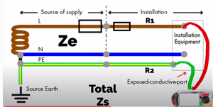
    Hmm - not so sure about that; R1 is always in series with the supply transformer.  Supplementary bonding can act to reduce the effect of R2 in the circuit, but R1 will always be there I think.  i.e. you can reduce the resistance/impedance of the return/earth path to the transformer, but the 'live' path in a fault condition is always going to be arriving via your live conductors.  So the total loop impedance is always going to be Ze (or Zs at source) + R1 + R2 (whatever R2 ends up being with the added benefit of supplementary bonding). I don't think you can ever reduce the total of R1 + R2 to below the value of R1 can you?

    b5f022b8c541fc43af08737196afc6be-original-image.png
  • Peter S3:

    Zs at DB should be the value of Ze plus the total R1+R2 of the total circuit feeding the DB right?  R2 might be reduced at a particular DB by local bonding, but there will always be some R1 which will generally act to increase the total Zs at DB as you add more DBs into the chain?


    See mapj1's posting above - the 4th response..


    I think that you are correct.


    I always think that it helps to draw out the installation.


    My algebra isn't what it used to be, but call the impedance of the conductors to the final DB R1a and R2a; and the impedance of the final circuit conductors R1b and R2b. Zs db = Ze + R1a + R2a. Zs at let's say a luminaire = Ze + R1a + R2a + R1b + R2b. Bolt that luminaire to the steel frame of a building which is bonded to the MET. Now assume that the parallel path through the building has a trivial impedance so R2a and R2b may be discounted. Zs now = Ze + R1a + R1b and Zs db = Ze + R1a + R2a. If Zs < Zs db, Ze + R1a + R1b < Ze + R1a + R2a i.e., cancelling the terms which are on both sides, R1b < R2a.


    So Zs of the final circuit will be lower than Zs db only if the parallel pathway has a trivial impedance and the impedance of the line conductor of the final circuit is less than that of the CPC of the distribution circuit. That would be most unusual!


    I hope that this makes sense - I could have done better 40 years ago!


  • Quite right - a Zs reading will always exceed R1 unless something very odd is happening.  What varies with location a is how much of of the R2 contribution  is  by the wire you think it is, and how much is bypassed back to somewhere nearer the source earth by conduit, girders, plumbing etc.

    And you can always get a high Zs at any point along  the line if that box of tricks is not as well earthed.as it should be, or if the 'live' chosen for probing purposes was a bit tarnished or scratchy (a plug in test at a slightly corroded wall socket perhaps)

    At the 10 milliohms level you do not need much to throw the readings quite a long way out.

    But in summary before paying for any re-work, get the inspector to correct the errors - there may well be more than you have shown us.
  • One thing that has not been mentioned is the possibility of a faulty tester, in combination with someone not alert enough to notice it.


    I have noticed this with our MFT 1730, Zs and R1R2 readings varying seemingly at random, despite new leads, and a recent calibration.


    On opening it up, a dry joint was found on the Green terminal (explaining why our prospective earth fault current was always lower than the L-N reading even at the origin on TN-C-S supplies)


    Cal labs won't always notice this if the dry joint happens to make good contact at that moment or because of the angle they insert the plug at.


    The discrepancy shown is very much in line with what we were finding... 0.0something at origin, but the next test on the same exact setting in the same exact place, in the 1.something range...
  • Former Community Member
    0 Former Community Member
    @MHRestorations: that is entirely possible- we note that the Cal date for his test meter was 2 days AFTER the date of the inspection...
  • Peter S3:
    @MHRestorations: that is entirely possible- we note that the Cal date for his test meter was 2 days AFTER the date of the inspection...


    I think that annual independant calibration is not the best way if used solely.

    lf A robust frequent checking even with something you built yourself is a good start.

    Before Calcard I built up a resistance box for a few continuity and ins res checks.

    A few sockets for loops and two RCD sockets for RCD tests (2 in case one failed).

    I run all the tests monthly or more frequently.

    I do not claim any great actual accuracy but it makes drifting easier to spot over a short period between such tests and a longer period overall. Not foolproof but has some benefit.


  • Peter S3:
    @MHRestorations: that is entirely possible- we note that the Cal date for his test meter was 2 days AFTER the date of the inspection...


    Don't consider that an issue, if you are running checks on your equipment throughout the year the period between calibration can extended for several years.


    I was told to get my testers calibrated after three years as a non-compliance and was muttering about it as I stood at the counter in my wholesalers as I was waiting to be served and drop them off for the calibration. There were comments that you must get them done every year from other electricians, my comment was if you cannot test your own testers and be confident that they are reasonably accurate you should not be out and about doing electrical testing with your meters. 


    If you can test electrical installations then you are capable of running interim tests on your own testers.


    It should also be noted that using the same loop meter to measure in different ways 2-wire Hi, 2-wire Low and 3-wire Low at the same point will give different test results, you may get a different result at a different time with the same tester using the same method and all of them will usually vary from Ze+ R1+R2. Using different loop tester will return a different set of results altogether. The should not be huge differences, but things like having a RCD in circuit can add significantly to the test result.


    I did the inspection and testing course along with the exam twenty odd years ago, digital meters were still relatively new products, my tutor passed comment that older electricians often went into melt down using digital meters. The older electricians would test using an analogue meter starting by twiddling the knob to zero it, then connect it and press test the button which sent the needle across the scale, they would try to look at the needle straight on to avoid parallax then take a reading as it wobbled about a bit, before announcing "That's okay" and writing a test result down.


    Now with digital meters you get a result taken as a sample recorded to two decimal places resulting in electricians going into meltdown reaching for tables, calculators and books to confirm that "it's a good result" when all you really want to know is if the fuse will blow or the trip will trip. So if the maximum Zs for a fuse or trip is 1.1 ohms and you have a test result much lower than that it's job done and time to move onto the next thing, unless you get what is obviously a high reading for a large or short cable, in which case the terminals may need checking or something similar.


    At times loop testing requires a bit of thought as to how and why you ended up with the result you got, also if it is an issue or not.


    There is an old saying "Learn to test, test to learn".


    Andy Betteridge


  • Former Community Member
    0 Former Community Member
    Hi peters3 you have done the right thing by querying this EICR, the few bits you have posted have so many anomalies that I am confident to say that the report you have is worth less than a single toilet roll, second hand, in terms it’s reflection on the installations current condition.


    Could you post the whole Report up just for fun? :)
  • Former Community Member
    0 Former Community Member
    Hi Weirdbeard.  Thank you for your confirmation regarding the report

    Hopefully you will find the full report attached for your entertainment!
    2020 EICR Redacted.pdf
  • Former Community Member
    0 Former Community Member
    And here is the previous EICR from 2015 for comparison.

    2015 EICR Redacted.pdf